batch tankLINK Technical Specifications

Features
- Nutrient Monitoring: Tracks EC and pH levels continuously to maintain optimal nutrient concentrations for every growth phase.
- Automated Fill Control: Prevents dry tanks with level sensors that automate refills, ensuring uninterrupted nutrient supply with minimal manual effort.
- Data Logging and Alerts: Logs sensor data for historical tracking and provides alerts for deviations, enabling proactive tank management.
What’s Included
x1 batch tankLINK
x1 AC/DC Power Supply
x1 Mounting Kit
x1 10 ft. RJ-45 Cable
x1 pH Probe
x1 EC Probe
x1 Temperature Probe
x1 Mini Screwdriver
x1 Level Sensor (Purchased Separately)
batch tankLINK Dimensions
4.625" (117mm) W
3.313" (84mm) H
1.313" (33mm) D
Installation & Wiring Instructions
Mounting the Enclosure
When possible, mount equipment outside of the growing environment for better service access and reduced exposure to humidity. If a batch tankLINK is to be installed in a humid growing environment, mounting in a sealed enclosure is recommended.
Follow these tips for best results:
- Install the batch tankLINK in a dry location away from drips or condensation.
- Ensure the batch tankLINK is accessible for service.
- Place the batch tankLINK in the area intended for mounting. Ensure there is adequate space for connections.
- Mark the hole locations and install anchors or pre-drill holes if necessary.
- Mount the enclosure to the wall or ceiling using mounting bracket.
Note:
Protect input jacks from dust or contamination during installation, cover ports with masking tape.
Connections
The batch tankLINK can be connected to a Growlink HUB, or to your WI-FI network as a stand-alone controller.
The batch tankLINK offers inputs for EC, pH, and temperature probes, as well as a level sensor.
LCD Screen: LCD panel for data and settings
HUB Connection Port: RJ-45 connection port
HUB LED Status Indicator: Indicates device power and HUB communication status.
LCD Screen Controls: LCD screen navigation control buttons (3x)
Temp/EC Ouput Terminal: Sends temperature and EC signal output.
Power Input: Input for 24VDC from included 24VDC power adapter.
ph Sensor Output: Sends pH signal to connected device.
Wi-Fi LED Status Indicator: Indicates Wi-Fi connection status.
Setup Button: Initiates setup mode and readdresses the batch tankLINK module.
Level Sensor Input: Connects to external level sensor device.
Connecting Sensors
pH sensors are equipped with “BNC” style connectors which push on and then turn
1/4 rotation CW to lock them in place. Temperature and Electrical Conductivity
Sensors have a screw terminal block; make the connections according to the
label on the transmitter. The terminal block may be removed for service.
LCD Menu Operations
The main screen displays real-time sensor readings from all connected sensors. Each
button is labeled along the bottom of the display, indicating its specific function based
on the current screen or menu.

Manufacturing Info
Manufacturer information such as serial number, date of manufacture, hardware and firmware versions can be read from the MFG INFO page.![]()

Main Menu
The main menu provides access to alarm settings, sensor calibration, and general
configuration options such as time, date, and units.

Setup Menu
The setup menu is where the time and date are set, the units are configured, logging
interval is adjusted.

Time and Date
BTL's include a precision real-time clock with battery back-up for time-stamping
the data log information with the time and date. The last calibration for each sensor is
also time stamped.
Units


Display Back Light Timer
Device Address
Logging Interval
Alarms Menu
High and Low alarm set points may be configured for each sensor for the BTL display . The out-of-range value will be displayed in red to indicate the cause for the alarm. These alarms do not populate within the Growlink Platform.
Additionally, alarm limits are plotted on the graphs to indicate values are within the
desired range.
Alarms Configuration
Graphing
The display on the BTLcan graph up to the most recent 120 data points from the sensor’s internal memory. With the default logging interval of 60 seconds, the graph provides a 2-hour view of recent sensor data.
Sensor values are plotted in green. If temperature is overlaid, it appears in red.
User-defined alarm levels are displayed in yellow.
Press the RFH button to refresh the data and update the graph.
High/Low History
The device tracks and stores the minimum and maximum values until manually reset.
To view the high and low readings since the last reset, press the H/L button.
To clear the history, press the RST button. This resets both the minimum and maximum
values to the current readings. New highs and lows will be recorded automatically as
they occur.
Calibration Menu
Calibration can be performed for each sensor with the LCD interface using the
calibration wizard.
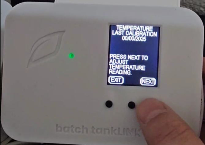
The date of the last calibration for each sensor is stored in memory and displayed at
the start of each calibration wizard.
Temperature Calibration
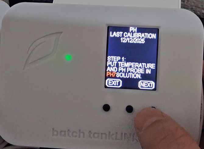
pH Calibration
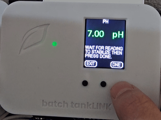
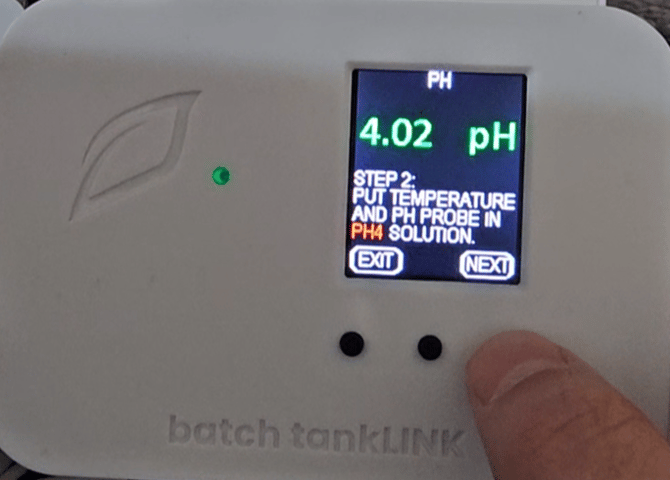
pH calibration is a two-point process requiring both pH 7 and pH 4.01 calibration
solutions. The temperature sensor must be inserted into the calibration solution at the
same time as the pH sensor.
Level Sensor Calibration
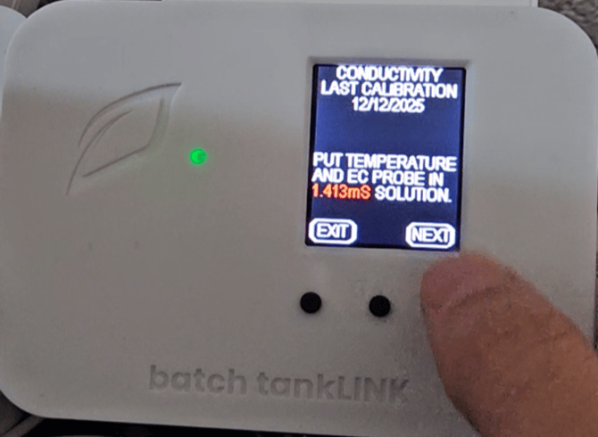
Conductivity Callibration
Conductivity calibration on a BTL is a single point process requiring 1413 uS calibration solution.The temperature probe must be inserted into the calibration solution at the same time as the conductivity probe.
Clear Calibration
The Instruction Manual for the batch tankLINK can be found below:
batch tankLINK Instruction Manual
Mobile App Setup Guide
1) Plug in your Growlink device to power it on. The LED should be blinking blue. If not, hold the SETUP button until status light flashes blue rapidly (12-15 seconds).
2) Download the Growlink app from the Apple App Store, or Google Play Store. 
3) Go to portal2.growlink.com/signup or tap the ‘Sign Up’ button at the login page of the Growlink Mobile App to create a Growlink Account:

After creating your account, a verification email will be sent from ‘no-reply@growlink.com’ to the email address set for your newly created account. One must verify your email address in order to utilize your newly created account.
4) Open the Growlink Mobile App and login to your newly created and verified account:

5) Tap the icon of three lines in the top-left of the Mobile App, then tap the Hardware button in the following menu.
6) One can add a controller to an existing room, or tap the ‘+Add’ button in the following page to add a new room to your account. This is the container that will hold the future controller registration.

7) If you are creating a new Room, provide a name for the Room, the Square Footage of the Room, and the Room Type, followed by tapping the 'Create’ Button to finish creating that room:
8) Once an existing room has been selected or a new room has been created, tap the ‘Continue’ button to begin registering the controller to your account.

9) Within the Add Hardware Wizard, tap the LINKS button in the following page:
10) Select the ‘Add Devices’ option to add the controller to the specified room:
11) Select the ‘batch tankLINK’ option in the following menu that populates:
12) If you’re registering your batch tankLINK as a standalone device, tap the ‘Add as a standalone Wi-Fi Device’ option. LINKS connected via WiFi can only connect to secured 2.4GHz networks and cannot connect to WiFi networks that are not secured with a password and/or 5GHz WiFi networks.
If you’re registering your batch tankLINK to a LINKS Hub, tap the ‘Add to a HUB’ option:
Further instructions on how to add equipment to an existing LINKS Hub can be found HERE.
13) If registering the batch tankLINK as a standalone controller, the app will then search for a nearby device in listening mode. Ensure your batch tankLINK is in listening mode by holding down the setup button for at least 3 seconds.
Once the batch tankLINK is paired to your phone, designate the network you wish to connect the batch tankLINK to and input the credential for that network:
Once WiFi credentials have been provided, all that is left is to name the controller and tap the ‘Next’ button on the following screen. The Mobile app will then attempt to register the controller to your account and pass those credentials towards the controller.
14) Once the batch tankLINK has been registered, the app will populate the current sensors being detected by the batch tankLINK, where you can then name the sensor inputs and register them to your batch tankLINK:
To skip a specific module from being registered to your batch tankLINK, tap the ‘Skip’ button at the bottom of the wizard. Once the sensors have been named to your liking and any required fields for the module have been designated, one can tap the ‘Register Device’ button to finish registering the batch tankLINK.
15) Once successfully connected, the following success message will display. Tap the ‘Add Equipment to this Controller’ to add more hardware to this controller, Tap the ‘Edit Controller Profile’ button to update the Controller Profile Settings, or tap the ‘Go to Room Dashboard’ button to view the dashboard for the newly connected controller:
Sensor Calibration
1) Once you have your batch tankLINK registered and installed you can start to calibrate your sensors. This is done on the batch tankLINK itself.2) First hit the menu button:

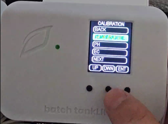
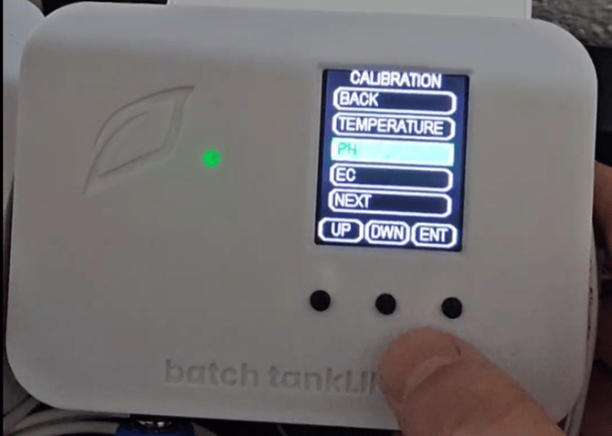
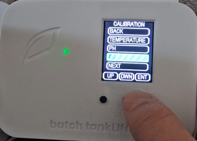
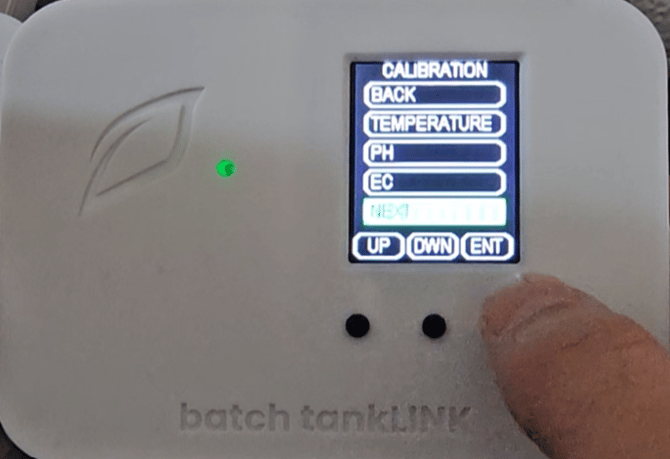
3) Then navigate to Calibration menu using the middle button:

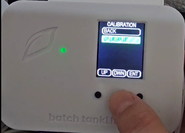
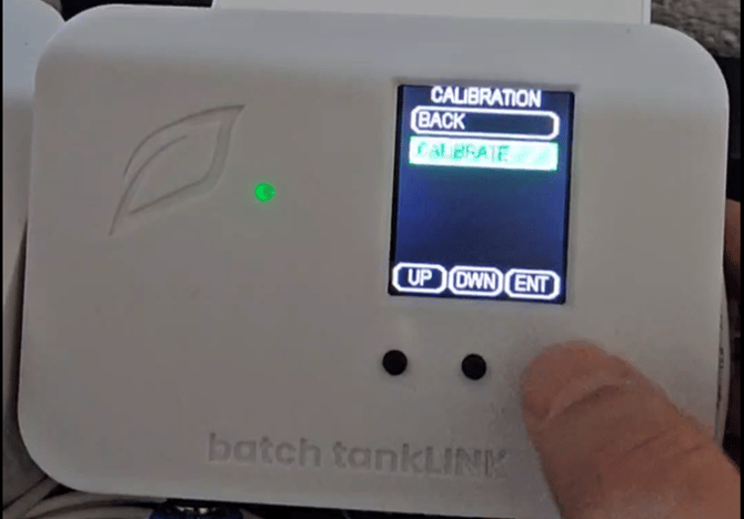
5) Then navigate to Calibrate and hit ENT:
6) Follow the on-screen directions once inside of this menu.
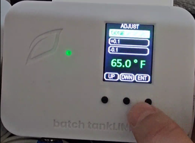
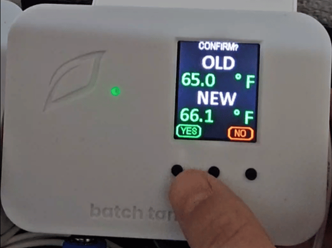
7) Adjust is for adding an offset to displayed value if you feel the reading needs adjustment.
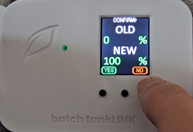
8) Accept the calibration by pressing YES (far left button):
9) Once you have finished calculating your Temperature Probe select pH:
10) Select Calibrate:
11) Follow the Direction on Screen and click NEXT:
13) Select Calibrate:

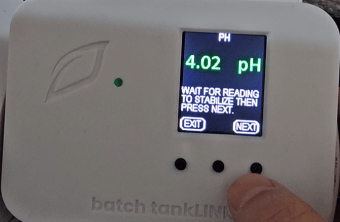
14) Follow the directions on the screen and click NEXT:
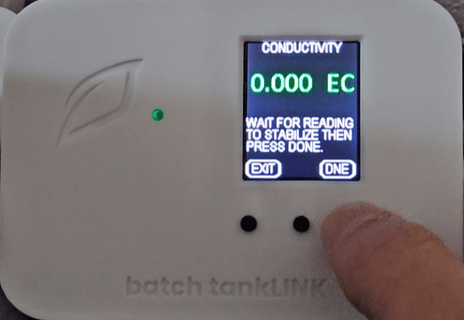
15) Wait for the readings to stabilize and click DNE:
16) If you purchased a level sensor you final step will be to calibrate it. Scroll down to Next in the Calibration menu:
17) Select Depth:
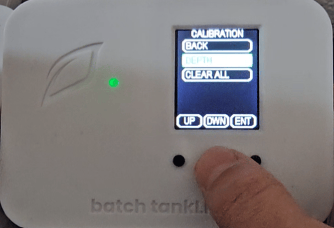
18) Then Select Calibrate:

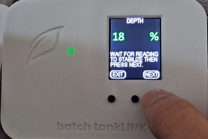
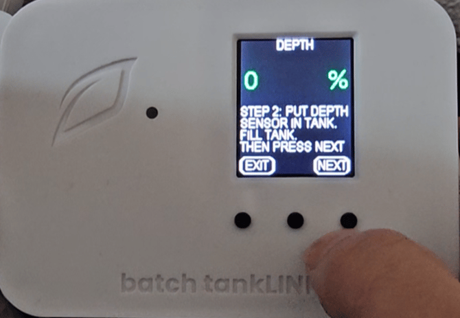
19) Follow the Directions on Screen and click Next:
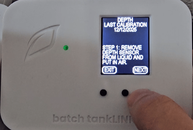
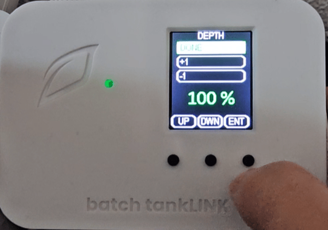
21) Click YES to finish the calibration if everything looks correct.
All Aspects of your batch tankLINK are now configured.
Troubleshooting
Controller not showing up on my list of devices to connect:
Check your phone or tablet and ensure Bluetooth is enabled.
Hold down the Setup button located on the controller (see image below) for approximately 12-15 seconds until there is a rapid flashing blue light. Then refresh the device list on your phone or tablet.
Unplug the unit for 10 seconds and then plug the device back in and wait for the LED lights to stop changing colors (typically 15 seconds). Then refresh the device list on your phone or tablet.
Controller didn’t connect to Wi-Fi:
If unsuccessful in the first attempt to connect the controller to the Wi-Fi network, hold down the Setup button located on the controller (see image below) for approximately 12-15 seconds until there is a rapid flashing blue light. Once rapid flashing becomes visible, immediately release the Setup button. This will put the controller into Listening Mode (Blinking Blue). Now, restart the connection process outlined in the Quick Setup Guide section above.
The Wi-Fi network being used has changed:
In the event the controller needs to re-connect to an existing or new Wi-Fi network, put the controller back into Listening Mode (see above) and follow the Controller Connection process outlined in the Quick Setup Guide section above.
Controller LED Status Light Color Codes
During device setup and operation, these are the LED light indicators:
- Solid White: Firmware Startup
- Slow Flashing Green: Wi-Fi connecting
- Fast Flashing Green: Wi-Fi waiting on IP address
- Fast Flashing Cyan: Wi-Fi connected, connecting to cloud
- Fast Breathing Green: Loading configuration and detecting probes
- Slow Breathing Green: Connected to cloud and running
- Slow Flashing Blue: Wi-Fi configuration mode
- Safe Mode: Slow breathing magenta
- Safe Mode Requested: Fast flashing magenta
- Firmware Updating: Slow flashing magenta
- Slow Flashing Blue: Wi-Fi setup mode