Table of Contents
Installation
- Mounting
- Electrical Power Installation
- Relay Wiring For On/Off Device Control
- Types of Relay Wiring (Dry vs. Wet Contact)
- Power Bus Wiring and Schematics
- Wet Contact Device Control & Detailed Wiring Instructions
- Dry Contact Device Control & Detailed Wiring Instructions
- Universal Input Wiring
- Analog Output Wiring
- BACnet MS/TP Wiring
Customer Service
At Growlink, we take pride in providing top-of-the-line customer support for our customers. Our team is dedicated to assisting you and your team in any way possible. To help us better serve you, please have the controller's serial number or controller name (if already registered with Growlink) ready before reaching out to our support team.
Contact Us
| Generate a Support Ticket: | Click Here to Create a Ticket |
| Email Support: | support@growlink.com |
|
Telephone: |
1 (800)-432-0160 |
Warranty
For information on our current Product Warranty Policy, please visit our website. Click here to view the details.
Return Policy
For information on our current Return Policy, please visit our website. Click here to view the details.
Specifications
| Power Requirements |
|
| Temperature |
|
| Onboard Voltage Outputs |
|
| Network Connections |
|
| Dimensions |
|
| Inputs / Outputs | |
| (x3) Power Bus |
|
| (x16) Solid State Relays (SSR) |
Each SSR Channel is rated as follows:
|
| (x4) Mechanical Relays |
Each Mechanical Relay is rated as follows:
|
| (x8) Analog Outputs |
|
| (x8) Universal Inputs (UI) |
|
| (x1) SDI-12 Channel |
|
| (x1) SDI-12 Addressing Port |
|
| (x1) RS485 Serial Port |
|
Connect Overview
Connect Input and Output Locations
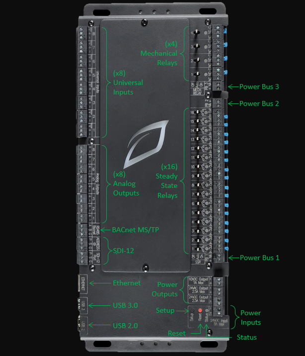
Ethernet
The Growlink Connect controller comes with an RJ45 Ethernet Port. Connecting this port to a Router or facility Network Switch that is connected to a reliable internet connection* allowing the user to access the Connect Controller setpoints and data from any location via the Growlink App or Web Portal.
*Requires a 5 Mbps or greater, low latency internet connection.
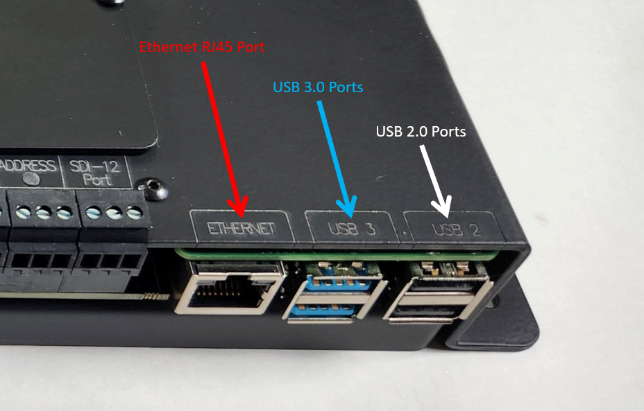
USB Ports should not be used for powering external devices such as smart phones, etc.
SDI-12 Overview
The Growlink Connect Controller comes with an SDI-12 Sensor Port that can be utilized for connecting Growlink Terralink or TDR Sensors for monitoring substrate data and an Addressing Port for use in automatically addressing the SDI-12 Sensors. Up to 36 sensors can be connected to the SDI-12 Port on the Connect, with sensors addressed to the range of 0-9 and A-Z. See the Detailed SDI-12 Wiring Section for specific information about connecting SDI-12 Sensors.
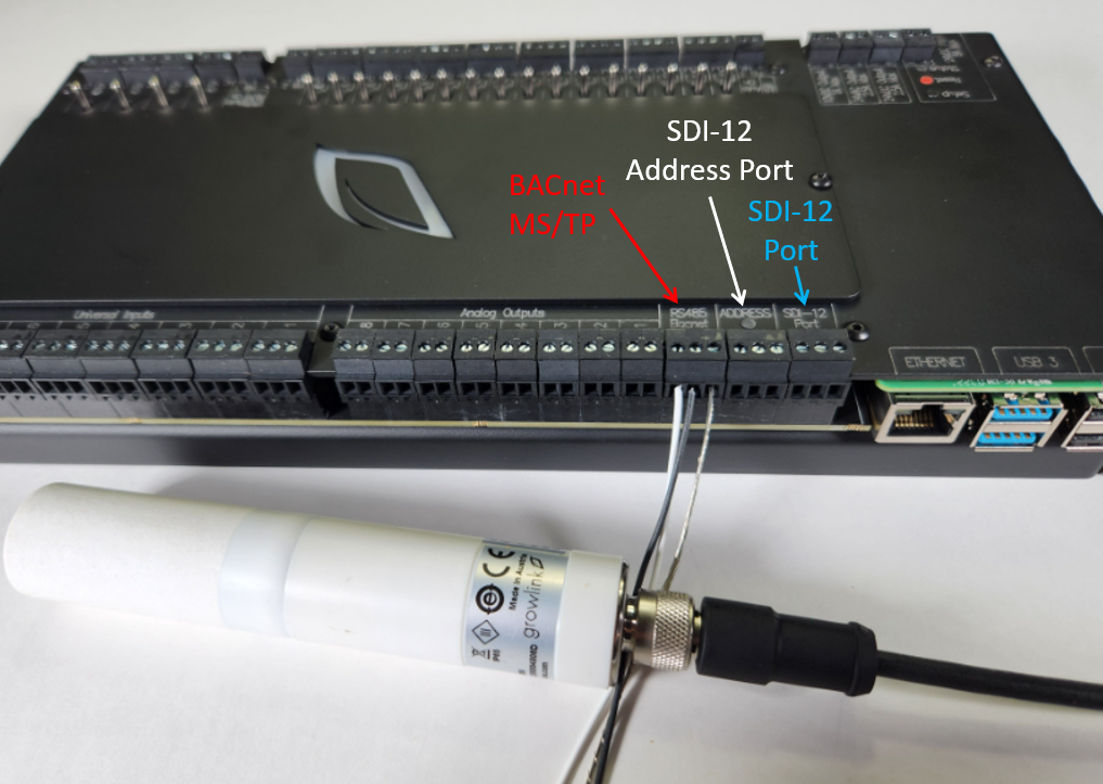
BACnet MS/TP Overview
The Connect Controller can accommodate BACnet MS/TP Connections and enables you to integrate with a variety of expansion modules, environmental sensors, and HVAC Units* or third-party equipment that can accommodate BACnet MS/TP setpoints. The Connect Controller can accommodate up to 32 Devices and sensors.
The Connect Controller BACnet Capabilities should be used for writing temperature and humidity setpoint information to each HVAC unit only and is not to be used for control of internal HVAC unit components. The Connect Controller is not a Front-End Building Management System.
Analog Outputs Overview
The Connect Controller has (x8) 0-10V Analog Outputs that can be used for providing 0-10V control signals to a variety of devices that accept 0-10V signals. Common controllable devices are:
- Modulating Valves
- Variable Frequency Drives (VFD)
- Variable Speed Drives (VSD)
- Fans (Speed control for Fans accommodating 0-10V)
- Light dimming zones
The Connect Controller can accommodate both sinking and sourcing light dimming control and each channel can accommodate up to 200mA of output making it the perfect solution for integrating with any grow light that can accommodate 0-10V Dimming signals.
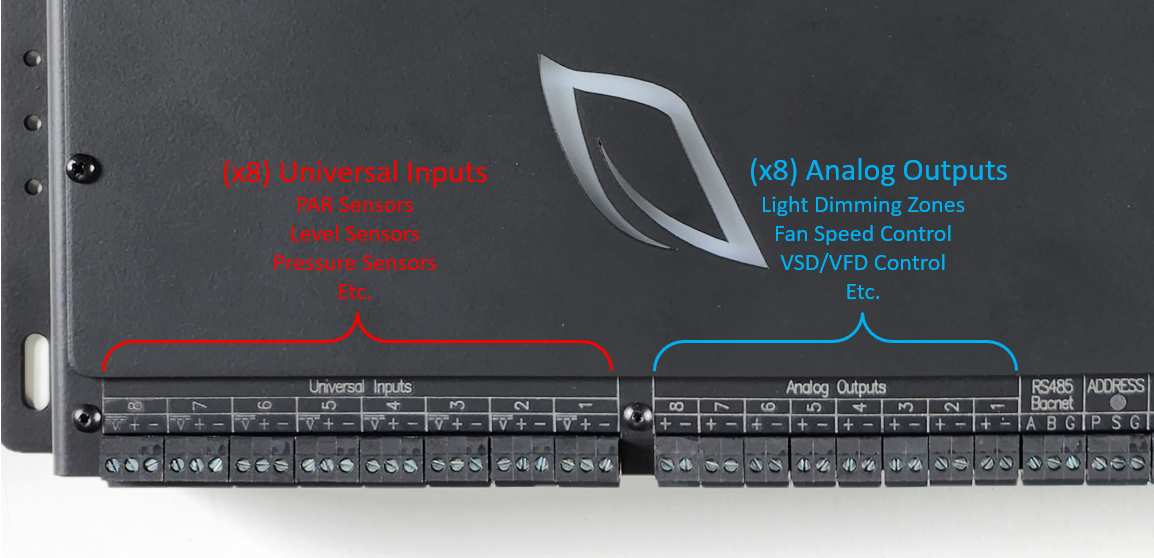
Universal Inputs Overview
The Connect Controller has (x8) Universal Input Channels that can each connect to and read from any sensor in your Grow that provides one of the following control signals:
0-10V
4-20mA
Resistive Input (Range: 760-500k Ω)
Digital Inputs
Common sensors that can be utilized with the Connect Controller are tank level sensors, PAR Sensors, pressure sensors, flow sensors, float switches, and any devices having dry contact alarm and/or 9-24VDC status output signal options.
Mechanical Relay Overview
The Connect Controller has four mechanical relay channels that function as Single Pole Double Throw (SPDT) relays for use controlling a variety of on/off devices, including two state devices in which a control signal is always applied to one of two device terminals, but not both. Each of the Mechanical Relay channels can be configured individually as either a Wet Contact or a Dry Contact depending on the type of device that is being controlled and how voltage is applied to that device.
For devices such as Irrigation Valves, Solenoids, Relay Coils, and Contactor Coils that typically require a 24VAC or 24VDC Wet Contact, the mechanical relays have a variety of wiring options based on the required voltage and current draw of the connected devices. The mechanical relays have one available Power Bus (Power Bus 3, PB 3) that can be utilized when supplying a common voltage (such as 24VAC) to multiple device types. See the “Wet Contact Device Control” section of this manual for more details on wiring Wet Contact devices and utilizing the built in Power Bus for the 4 Mechanical Relay Channels.
Each of the mechanical relay channels can also be configured as a Dry Contact for controlling external equipment that accommodates low voltage wiring control, such as dehumidifiers, heaters, and HVAC units controlled by traditional low-voltage thermostats. Each Mechanical Relay Channel can also be configured as a Dry Contact and utilized in situations where external power needs to be supplied to an individual relay directly and not through the Power Bus.
(x4) Mechanical Relay Channel Quick Reference:
Each individual SSR Channel as the following ratings:
- Maximum Amperage: 3A
- Maximum AC Voltage: 48VAC
- Maximum DC Voltage: 48VDC
- Jumper Removed: Dry Contact
- Jumper Installed: Wet Contact supplied voltage from Power Bus
WARNING: Never connect differing voltages to the same power bus. When connecting externally sourced power to an individual Mechanical Relay Channel, ensure that the jumper has been removed from that channel before connecting the power source.
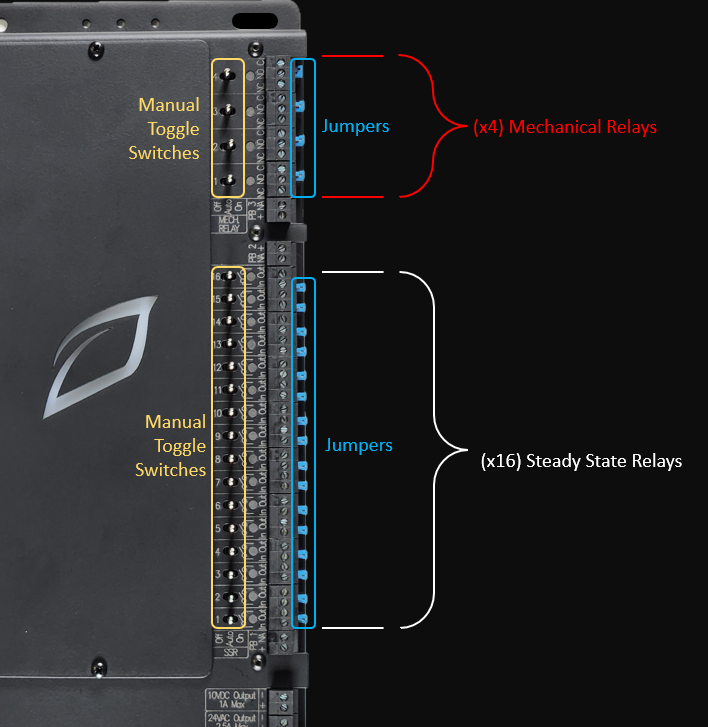
Solid State Relays (SSR) Overview
The Connect Controller’s 16 Solid State Relays (SSR) channels can be used for controlling a variety of on/off devices. Each of the 16 SSR channels can be configured individually as either a Wet Contact or a Dry Contact depending on the type of device that is being controlled and how voltage is applied to that device.
For Devices such as Irrigation Valves, Solenoids, Relay Coils, and Contactor Coils that typically require a 24VAC or 24VDC Wet Contact, the connect controller has a variety of wiring options based on the required current draw of these devices. The Connect Controller has two available Power Buses that can be utilized when supplying a common voltage (such as 24VAC) to multiple device types utilizing the same voltage. See the “Wet Contact Device Control” section of this manual for more details on wiring Wet Contact devices and utilizing the Connect Controller’s two built in Power Busses for the 16 SSR Channels.
Each of the 16 SSR Channels can also be configured as a Dry Contact for controlling external equipment that accommodates low voltage wiring control, such as dehumidifiers, heaters, and HVAC units controlled by traditional low-voltage thermostats. Each SSR Channel can be configured as a Dry Contact and utilized in situations where external power needs to be supplied to an individual relay directly.
16 Steady State Relay (SSR) Channel Quick Reference:
Each individual SSR Channel as the following ratings:
- Maximum Amperage: 3A
- Maximum AC Voltage: 38VAC
- Maximum DC Voltage: 48VDC
- Jumper Removed: Dry Contact
- Jumper Installed: Wet Contact supplied voltage from Power Bus
WARNING: Never connect differing voltages to the same power bus. When connecting externally sourced power to an individual Steady State Relay (SSR) Channel, ensure that the jumper has been removed from that channel before connecting the power source.
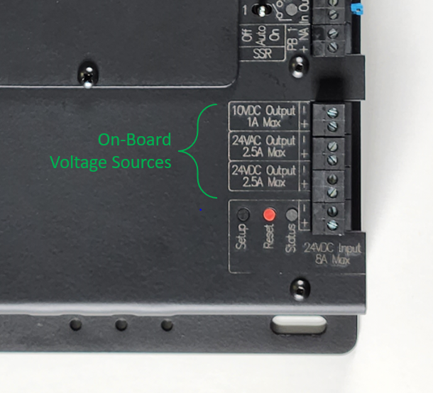
Onboard Voltage Source Options:
The Connect Controller has three voltage output terminals capable of providing 24VAC, 24VDC or 10VDC voltage source to the various relays, power buses, devices, and sensors that require them. Utilizing these power outputs can prevent the need for additional transformers and power supplies unless the current rating for these outputs would be exceeded with the connected equipment.
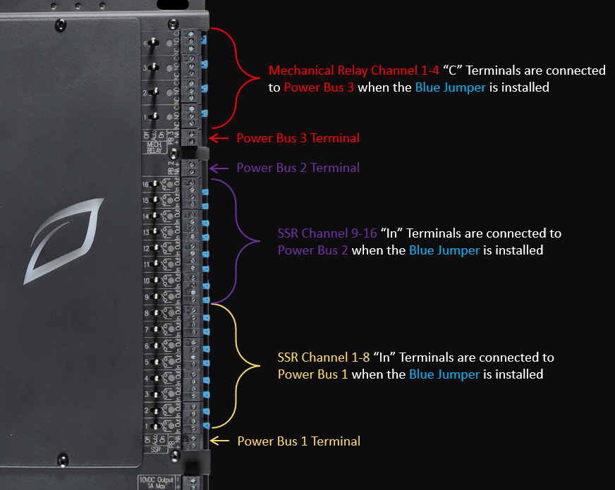
Power Bus Overview
The Connect Controller has (x3) Power Buses. Power Bus 1 is for use with Steady State Relay (SSR) Channels 1-8, Power Bus 2 is for use with Solid State Relay (SSR) Channels 9-16, and Power Bus 3 is for use with Mechanical Relay Channels 1-4.
Each of these power buses can be utilized to provide a common voltage source to each of the relays connected to that bus. This voltage source can come from the Connect Controllers Onboard 24VAC or 24VDC Output Terminals or an external voltage source can be provided to the bus (from an external AC Transformer or DC Power Supply).
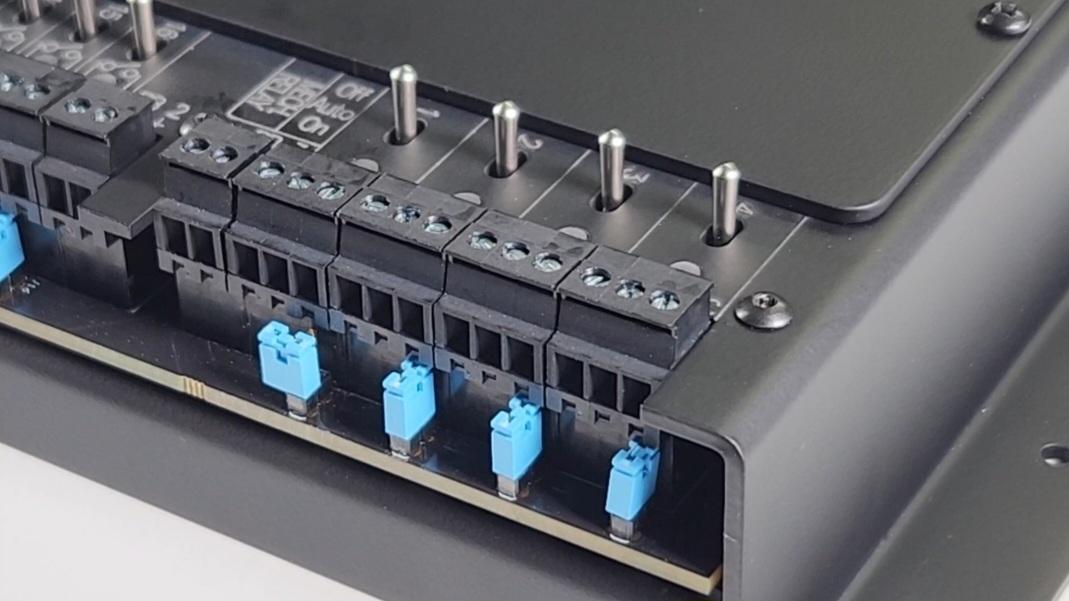
A blue Jumper is installed under the removable terminal blocks for each relay and this jumper may be removed to turn each relay into a Dry Contact, breaking the connection with the power bus and allowing that individual channel to operate independent of the voltage source applied to the power bus.
Power Bus Quick Reference:
Each Power Bus can accommodate the following:
- Maximum Amperage: 3A
- Maximum AC Voltage: 38VAC
- Maximum DC Voltage: 48VDC
- Each Power Bus may have only 1 type of Source Voltage Connected to it.
- Removing the Blue Jumper from a Steady State Relay (SSR) or Mechanical Relay channel disconnects that relay from the Power Bus and converts that relay into a Dry Contact.
WARNING
Never connect differing voltage sources to the same power bus. When connecting a voltage source to an individual Steady State Relay (SSR) or Mechanical Relay Channel, ensure that the jumper has been removed from that channel before connecting the power source.
Mounting
Package Contents Inspection
Before starting the installation process, it is highly recommended to inspect the package contents to ensure all necessary hardware is included. Please keep in mind that different applications require different equipment, so it is important to check the original invoice and packing slips for the specific hardware required for your installation.
Standard Package Contents:
- Connect Controller
- 24VDC / 8A Power Supply
Examples of auxiliary hardware include:
- Indoor environment sensors (ESM-2)
- Substrate media sensors (Terralink)
- Outdoor weather sensors
- Quantum PAR or Light sensors
If there is any visible damage to any hardware please contact our customer service team using one of the methods described above in the Customer Service Section.
Recommended Materials (Not Provided by Growlink)
- NEMA 5 rated enclosure large enough to house the Connect Controller.
- Water-tight cable glands or water-tight conduit fittings.
- Mounting hardware appropriate for the mounting surface of your choice.
Recommended Tools
- Drill
- Impact Driver
- Drill bit set
- Socket wrench and full socket set with 3"+ extensions
- 3/32" flat blade screwdriver
- #2 Philips head screwdriver
- Adjustable Wrench
- Level
- Pencil
Mount the Connect Controller
The Connect Controller must be properly grounded, regardless of mounting method. The controller housing must have a bonded path to Ground.
- It is highly recommended to protect the Connect Controller from environmental damage by mounting inside of a water-tight enclosure with the necessary hardware to secure it. Growlink's warranty is limited to manufacturer's defects and does not cover damage incurred due to improper installation or inadequate environmental protection. Please take the necessary precautions to protect your investment in your advanced Connect Controller.
- Determine the controller mounting location. The right location includes the following:
- It is important to choose a secure location inside the facility where it is protected from direct sunlight, humidity, rain, and extreme temperatures.
- An easily accessible location that is at eye level for the user. The preferred mounting height in most applications is 6ft (1.83M) to the finished floor.
- A 120V power outlet should be located within 6ft of the Connect Controller. This distance allows the provided power supply to be plugged into the outlet and the Connect Controller.
- To ensure ease of service and installation, it's recommended to have adequate workspace around the Connect Controller. This clearance will vary based on the size of enclosure used if an enclosure is chosen.
- Next, identify the surface type the Connect Controller will be mounted to. The type of hardware needed varies with each mounting surface. Choose hardware appropriate to mount either the Connect Controller or the enclosure chosen to house the Connect Controller to the mounting surface.
- Ensure the Connect Controller is bonded to ground by connecting a grounding cable to the mounting connections.
- Use the appropriate tools to mount the controller to the surface of choice. Use a level placed on the top of the enclosure to ensure the controller is level before permanently mounting.
Electrical Power Installation
The Connect Controller comes standard with a 24VDC / 8A power supply for a quick and easy set up.
- Plug the barrel connector of the provided power supply into the 24VDC Power port on the Connect Controller.
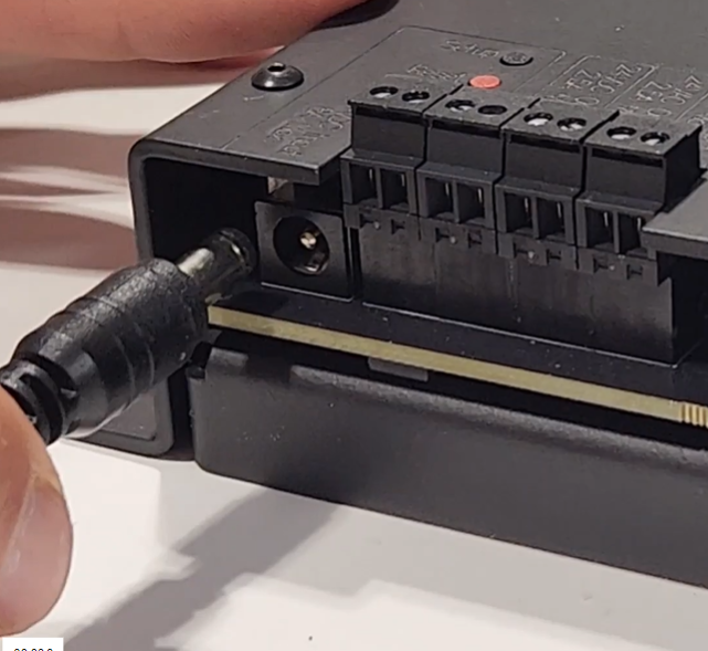
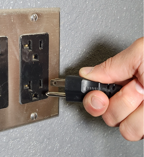
- Connect the power supply's standard wall plug into the 120VAC receptacle located near where the Connect Controller has been mounted.
Relay Wiring for On/Off Device Control
Overview
The Connect Controller is designed for flexibility in output control signal types in mind. Different pieces of equipment used in Controlled Environment Agriculture facilities require different control signals. This is why each Digital Output (Steady State and Mechanical Relays) can be configured in various ways to suit the needs of the equipment in your facility. We provide many generic examples of how different equipment interfaces with the Connect Controller but it is your responsibility as the installer to determine what signal each piece of equipment requires. Once this information is known, use the guides below to configure each output for the control type needed.
Types of Relay Wiring
When wiring a device to the Connect Controller Solid State Relay or Mechanical Relay Channels, there are two broad categories to consider:
- Wet Contact Device Control - Device Control Signal sourced from Connect Controller or from the Connect Controller Power Buses. (Solenoid valves, relays, contactors)
- Dry Contact Device Control - Device Control Signal sourced from the device or an external power supply. (Dehumidifiers, traditional HVAC units, heaters, etc.)
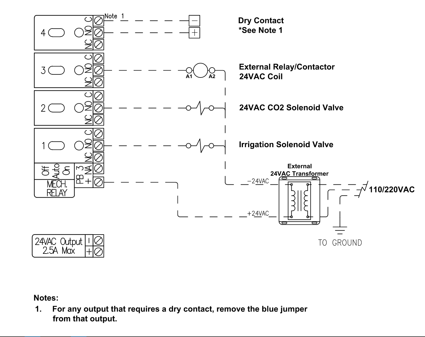
Power Bus Wiring and Schematics
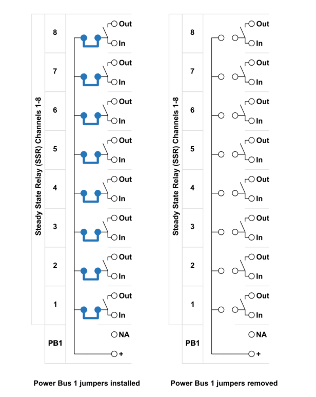
Power busses are provided to simplify the wiring needed for controlling many devices which all require the same control signal type. They provide low voltage power of your choice to all associated channels with one simple wiring connection. The schematics below show the connections between each Power Bus and the solid state or mechanical relay channels that bus is associated with. When a SSR or mechanical relay channel's blue jumper is installed, the Power Bus and that Channels “In” (SSR) or "C" terminal (Mech. Relay) are electrically connected. Removing the blue jumper isolates the relay channel from the power bus, allowing it to be used as a Dry Contact.
The blue jumper must always be removed for Dry Contacts and for relays that are supplied voltages independent of the power bus voltage source. See Jumper Removal Instructions below to learn how to isolate individual output channels.
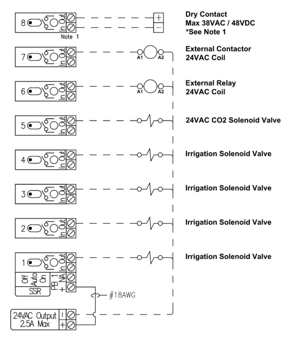
Power Bus 1 (PB1) and SSR Channels 1-8 Schematic
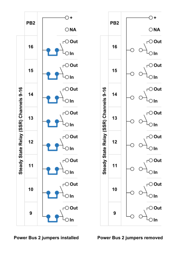
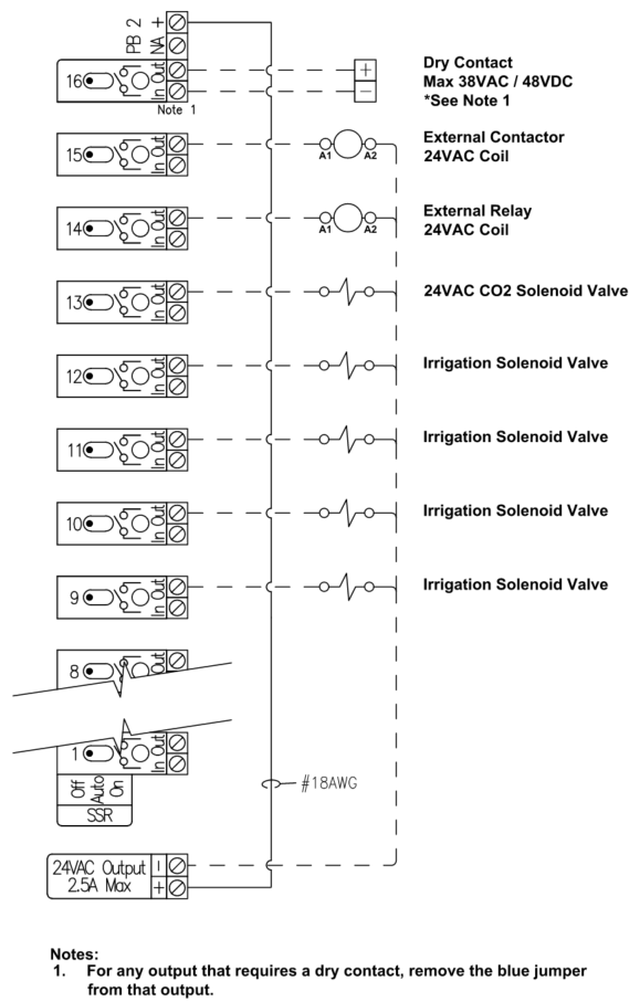
Power Bus 2 (PB2) and SSR Channels 9-16 Schematic
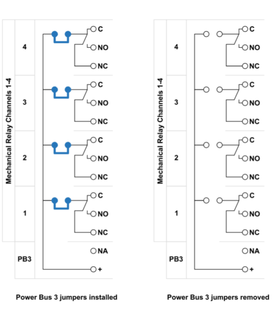
Power Bus 3 and Mechanical Relays 1-4 Schematic
Wet Contact Device Control
Many devices require a voltage source be provided to the device for it to operate due to it not having any other power source. Examples of such devices are Irrigation Valves, Solenoids, and Relay or Contactor Coils. When these types of controlled devices source this power from the Connect Controller directly, it's known as a Wet Contact.
For the purposes of this Manual “Wet Contact” is defined as any relay that provides control signal power to the controlled device using the onboard power busses connected to the “In” Terminal of the relay. See the Power Bus Section of this manual for more detail.
The Connect Controller has 24VAC, 24VDC and 10VDC onboard voltage source terminals that can be utilized to provide a Wet Contact control by connecting the outputs of these voltage sources to one or more of the Connect Controller’s Power Buses. Using these onboard Power Buses allows you to supply a common voltage to all or some of the relay channels associated with that bus. See the Power Bus Section for more detail.
Supplying Connect Onboard Voltage Sources to the Power Bus
Supplying Onboard 24VAC to Power Bus 1 and/or 2 (SSR Channels 1-8 and 9-16)
The Connect Controller can provide up to 2.5A total of 24VAC when utilizing the onboard 24VAC Output Terminal.
For situations in which all 24VAC Devices connected to the controller would collectively consume greater than 2.5A, an appropriately rated external 24VAC Transformer (not provided by Growlink) must be utilized so the onboard 24VAC Output Terminal is not exceeded. See Supplying External 24VAC to Power Bus 1 and/or 2 (SSR Channels 1-16) for details.
- Turn all toggle switches of the channels being wired to the "Off" position. This saves the channel fuse from accidentally being blown during device wiring and installation.
- Ensure that each SSR Channel utilizing the 24VAC Power from Power Bus has the Blue Jumper Installed.
- Connect the (+) Terminal of “24VAC Output” to the PB 1 or PB 2 (+) Terminal. This creates a common connection between the 24VAC Power and the “In” Terminal of each channel on the Power Bus (unless a particular channel's Jumper is removed).
- For each channel connect the “Hot” wire of the 24VAC device to the “Out” Terminal of the channel responsible for controlling that device.
- Connect the “Neutral” wire of each 24VAC device sourcing 24VAC power from the Power bus back to the 24VAC Output (-) Terminal.
Important Note: Only one master neutral wire should be connected to the Connect Controller's 24VAC Output (-) terminal (Max of 12AWG). Use only appropriate external multi-wire connection devices (wire nuts, Wago® lever nuts, terminal blocks, etc.) to connect multiple neutral wires together before landing a single neutral wire back to the 24VAC Output (-) terminal.
Example Wiring: Onboard 24VAC Connected to Power Bus 1 (PB 1)
Example Wiring: Onboard 24VAC Connected to Power Bus 2 (PB 2)
Supplying Onboard 24VAC to Power Bus 3 (Mechanical Relay Channels 1-4)
- Turn all toggle switches of the channels being wired to the "Off" position. This saves the channel fuse from accidentally being blown during device wiring and installation.
- Ensure that each Mechanical Relay channel utilizing the 24VAC Power from Power Bus 3 has the Blue Jumper Installed. This applies to Mechanical Relay Channels 1-4.
- Connect the (+) Terminal of the “24VAC Output” to the PB 3 (+) Terminal. This creates a common connection between the 24VAC Power and the “C” Terminal for Mechanical Relay 1-4 (unless a channel's Jumper is removed).
- For each channel connect the “Hot” wire of that 24VAC device to the “NO” Terminal of the channel responsible for controlling that device.
- Connect the “Neutral” wire of each 24VAC device sourcing 24VAC power from the Power bus back to the 24VAC Output (-) Terminal.
Important Note: Only one master neutral wire should be connected to the Connect Controller's 24VAC Output (-) terminal (Max of 12AWG). Use only appropriate external multi-wire connection devices (wire nuts, Wago connectors, terminal blocks, etc.) to connect multiple neutral wires together before landing a single neutral wire back to the 24VAC Output (-) terminal.
Example Wiring: Onboard 24VAC Connected to Power Bus 3 (PB 3)

Supplying The Connect Power Busses with an External Power Source
When required (ie. total amperage required exceeds 2.5A), external power supplies and transformers can be utilized to provide the Wet Contact control needed for devices. External power supplies and transformers can be connected to the Connect Controller Power Buses to enable this.
For Connecting External Power Supplies and Transformers to individual relays and not through the power bus, see the Dry Contact Section.
Alternatively, these external devices can be connected to a relay as a Dry Contact for supplying power to individual devices and not through the Power Bus (See the Dry Contact Section for more information).
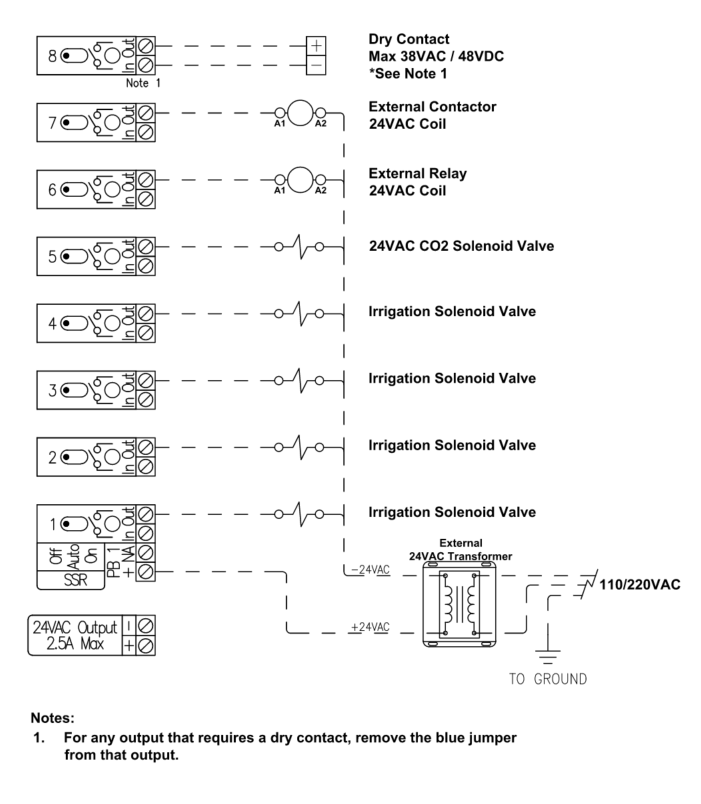
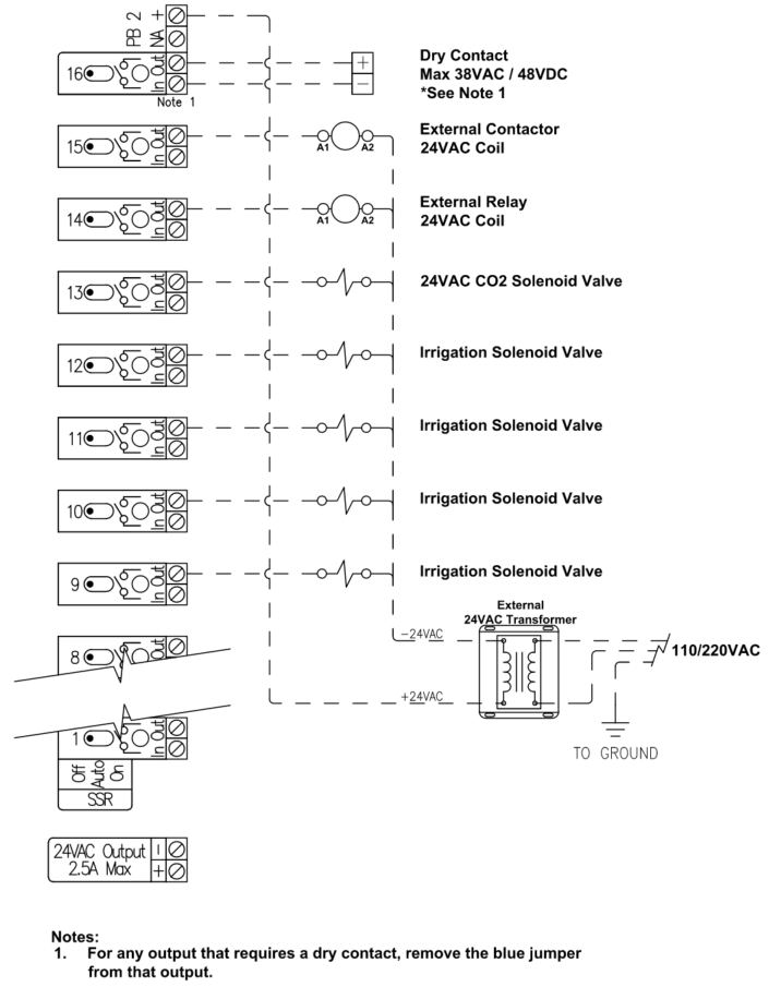
Supplying External 24VAC to Power Bus 1 and/or 2 (SSR Channels 1-8 and 9-16)
- Turn all toggle switches of the channels being wired to the "Off" position. This saves the channel fuse from accidentally being blown during device wiring and installation.
- Ensure that each SSR Channel utilizing the 24VAC Power from Power Bus has the Blue Jumper Installed.
- Connect the Supply side [i.e., the Hot or 24VAC (+)] of the External Transformer to the PB 1 and/or PB 2 (+) Terminal. This creates a common connection between the External 24VAC Transformer output and the “IN” Terminal of each channel on the power bus (unless a channel's Jumper is removed).
- For each channel connect the “Hot” wire of the 24VAC device to the “Out” Terminal of the channel responsible for controlling that device.
- Connect the “Neutral” wire of each 24VAC device sourcing 24VAC power from the Power bus back to the 24VAC Neutral Side of the External 24VAC Transformer.
Important Note: Use only appropriate external multi-wire connection devices (wire nuts, Wago connectors, terminal blocks, etc.) to connect multiple wires together.
Example Wiring: 24VAC external transformer connected to Power Bus 1 (PB 1)
Example Wiring: 24VAC external transformer connected to Power Bus 2 (PB 2)
Supplying External 24VAC to Power Bus 3 (Mechanical Relay Channels 1-4)
- Turn all toggle switches of the channels being wired to the "Off" position. This saves the channel fuse from accidentally being blown during device wiring and installation.
- Ensure that each Mechanical Relay channel utilizing the 24VAC Power from Power Bus 3 has the Blue Jumper Installed. This applies to Mechanical Relay Channels 1-4.
- Connect the Supply side [i.e., the Hot or 24VAC (+)] of the External Transformer to the PB 3 (+) Terminal. This creates a common connection between the External 24VAC Transformer output and the “C” Terminal for Mechanical Relays 1-4 (unless a channels Jumper is removed).
- For each channel connect the “Hot” wire of that 24VAC device to the “NO” Terminal of the channel responsible for controlling that device.
- Connect the “Neutral” wire of each 24VAC device sourcing 24VAC power from the Power bus back to the 24VAC Neutral Side of the External 24VAC Transformer.
Important Note: Use only appropriate external multi-wire connection devices (wire nuts, Wago connectors, terminal blocks, etc.) to connect multiple neutral wires together before landing a single neutral wire back to the 24VAC Output (-) terminal.
Example Wiring: 24VAC external transformer connected to Power Bus 3 (PB 3)
Dry Contact Device Control & Detailed Wiring Instructions
A Dry Contact is used in two distinct situations:
- When the device being controlled is, itself, supplying a low voltage source to the controller relay and then the controller supplies that voltage back to the device's activation terminal(s) when needed. Common examples of Dry Contact Control include dehumidifiers, heaters, and HVAC units controlled by traditional low-voltage thermostats.
- When a controlled device is supplied with an external power source through the relay directly (i.e. when not utilizing the Connect Controller’s Power Bus to provide power to the output).
When Using a Solid State Relay or Mechanical Relay as a Dry Contact you must remove the Blue Jumper for that Relay Channel. See the Jumper Removal Instructions below for specific steps on how to configure a Relay for Dry Contact Control.
Relay Jumper Removal
Removing a Solid State Relay or Mechanical Relay Channel’s Jumper is required any time you are converting the relay channel into a Dry Contact or providing a voltage source to that relay directly and not through the associated power bus. To remove and store a Blue Jumper, watch this short video and follow these steps:
- Pull the Black Screw Terminal Block for the channel away from the front of the controller to remove it. It's designed to be removed in this manner.
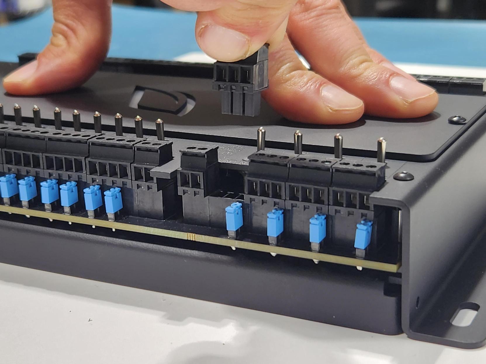
- Pull the Blue Jumper associated with the relay channel straight off the small metal pins, taking care not to bend the pins.
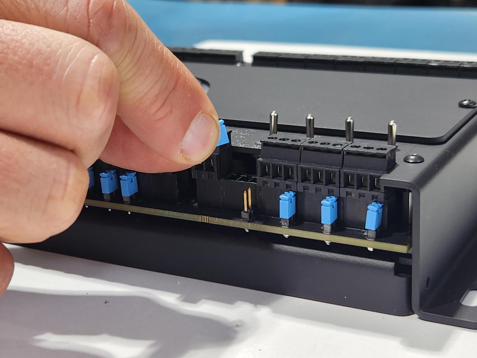
- Make sure to store the Blue Jumper for potential future use. Connect one part of the jumper to the outside jumper pin you just pulled it off, but keep the inside pin disconnected. This will ensure the jumper is readily available should it be needed in the future.
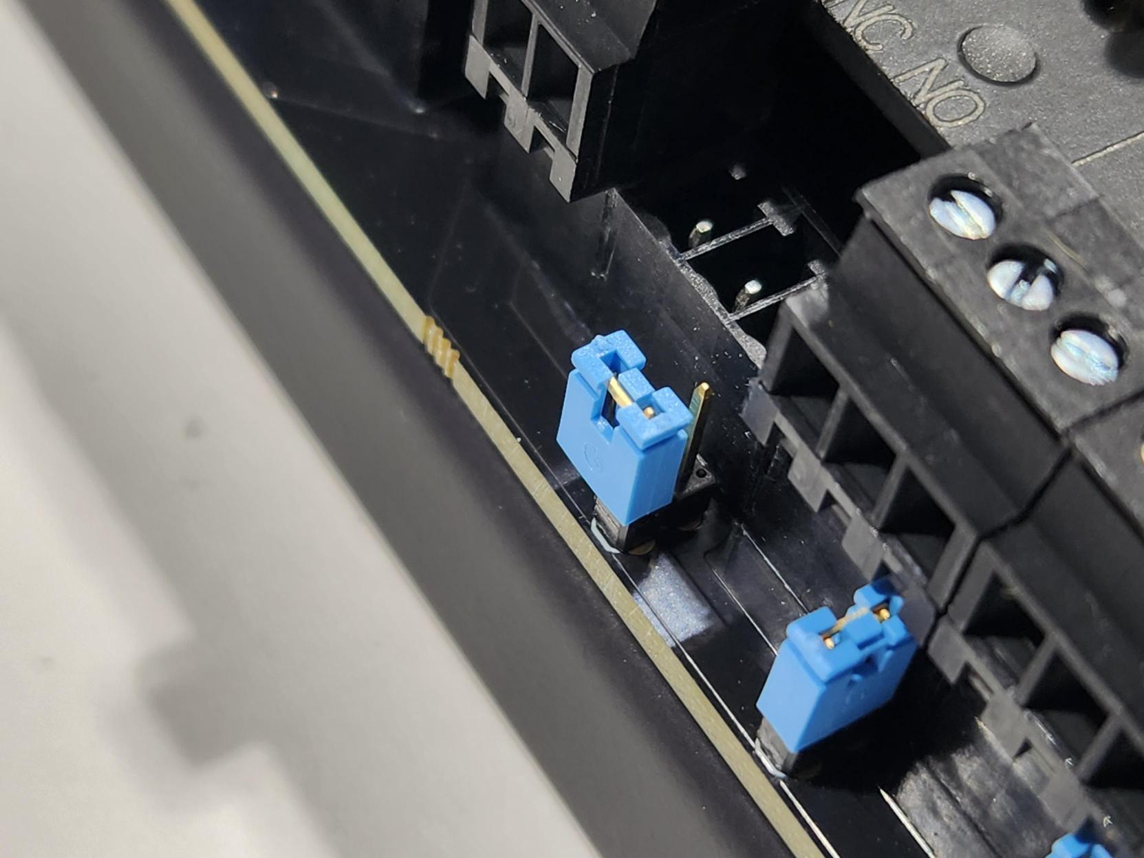
- Replace the Black Terminal Block in the original location it was removed from.
- Wire the device/voltage source requiring a dry contact to the terminals for that channel.
Configure a Solid State Relay Channel as a Dry Contact
- Ensure that each SSR Channel that needs to be a Dry Contact has the Channel Jumper removed. Refer to the Relay Jumper Removal Section for details on this process.
- Turn all toggle switches of the channels being wired to the "Off" position. This saves the channel fuse from accidentally being blown during device wiring and installation.
- Terminate the Supply Voltage from the Controlled Device to the SSR Channel “In” Terminal
- Terminate the Signal/Return Wire from the Controlled Device to the SSR Channel “Out” Terminal
Wiring Example: Typical 5-Ton HVAC Unit w/ a Single Cooling and Heating Stages.
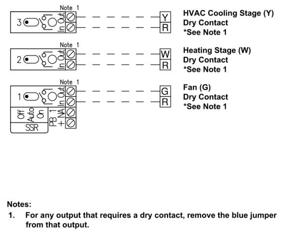
In the above example, Voltage is Sourced from the HVAC Unit “R” Terminal (Typically 24VAC Power). Although it's not shown, this "R" wire can be jumped across the "In" relay terminals rather than supplying an individual "R" wire to each channel.
Configure a Mechanical Relay Channel as a Dry Contact
- Ensure that each Mechanical Relay Channel that needs to be a Dry Contact has the Channel Jumper removed. Refer to the Relay Jumper Removal Section for details on this process.
- Turn all toggle switches of the channels being wired to the "Off" position. This saves the channel fuse from accidentally being blown during device wiring and installation.
- Terminate the Supply Voltage from the Controlled Device to the Relay Channel “C” Terminal
- Terminate the Signal/Return Wire from the Controlled Device to the Relay Channel “NO” Terminal
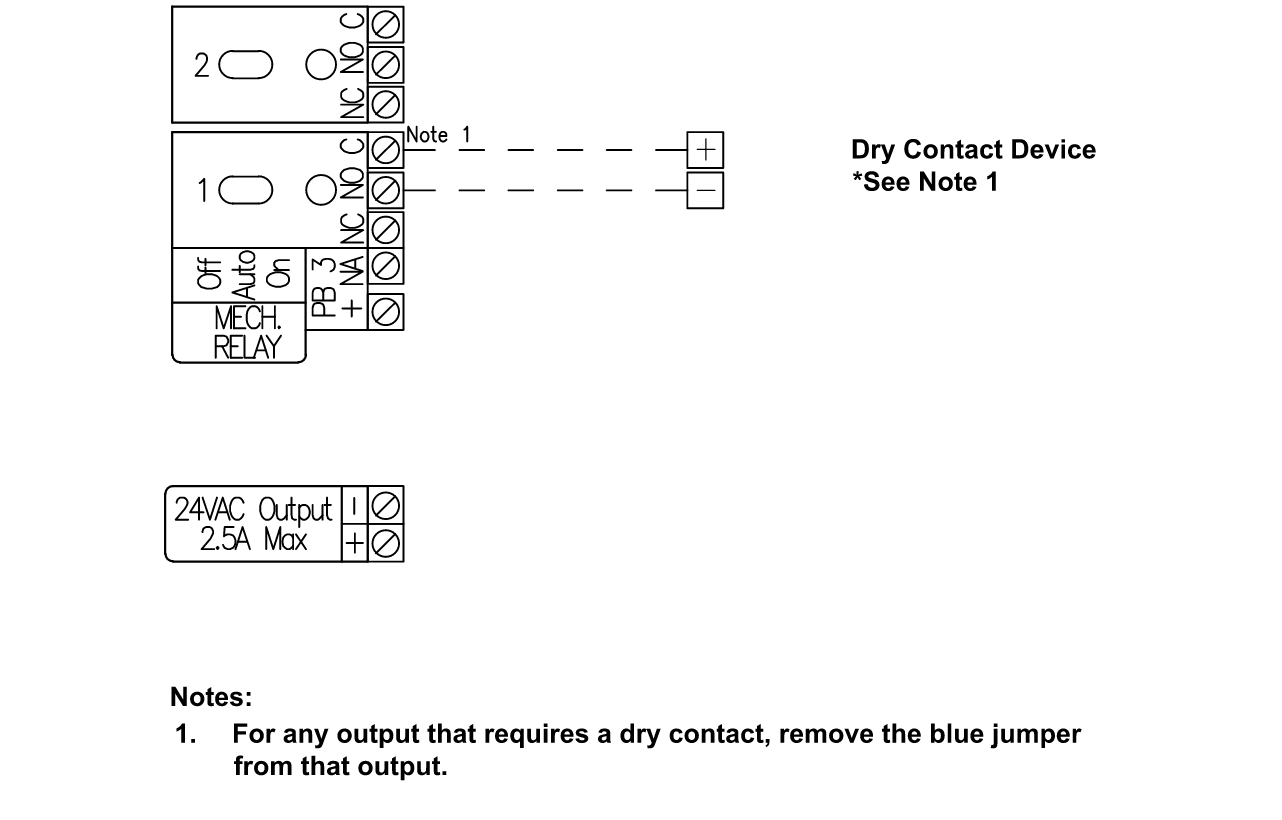
Wiring Example: Dry Contact Device connected to Relay 1
Supplying Power Sources to Individual Relays
When you need to provide a voltage source for device control through an individual relay channel that is not connected to the power bus, you can do so by configuring the channel as a dry contact and supplying the voltage source (Onboard or External Voltage Sources).
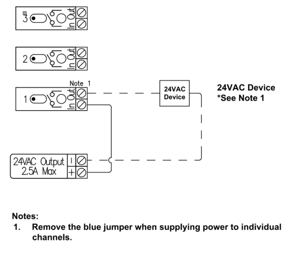
Supplying Onboard 24VAC to an Individual SSR
When you need to provide 24VAC to a device connected to a Solid State Relay Channel and 24VAC is not supplied to the Power Bus you can connect that relay channel to the Connect Onboard 24VAC output using the following steps.
- Turn all toggle switches of the channels being wired to the "Off" position. This saves the channel fuse from accidentally being blown during device wiring and installation.
- Ensure that each SSR Channel utilizing the 24VAC Power directly has the Jumper Removed.
- Connect the (+) Terminal of the “24VAC Output” to the “IN” Terminal for the SSR Relay.
- Connect the “Hot” wire of the 24VAC device to the “Out” Terminal of the channel responsible for controlling that device.
- Connect the “Neutral” wire of each 24VAC device sourcing 24VAC power from the relay back to the 24VAC Output (-) Terminal.
Important Note: Only one master neutral wire should be connected to the Connect Controllers 24VAC Output (-) terminal (Max of 12AWG). Use only appropriate external multi-wire connection devices (wire nuts, Wago connectors, terminal blocks, etc.) to connect multiple neutral wires together before landing a single neutral wire back t
o the 24VAC Output (-) terminal.
Example Wiring: 24VAC Onboard Output connected directly to SSR Channel 1
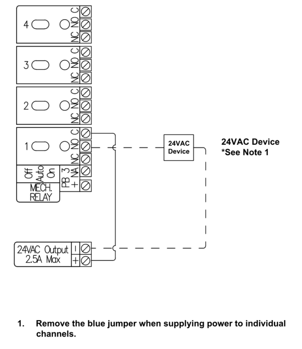
Supplying Onboard 24VAC to Individual Mechanical Relays
When a device connected to a Mechanical Relay Channel requires 24VAC and 24VAC is not supplied to the Power Bus, that Relay channel can be connected to the Connect Onboard 24VAC output using the following steps:
- Turn all toggle switches of the channels being wired to the "Off" position. This saves the channel fuse from accidentally being blown during device wiring and installation.
- Ensure that each SSR Channel utilizing the 24VAC Power directly has the Jumper Removed.
- Connect the (+) Terminal of the “24VAC Output” to the “IN” Terminal for the SSR Relay.
- Connect the “Hot” wire of the 24VAC device to the “Out” Terminal of the channel responsible for controlling that device.
- Connect the “Neutral” wire of each 24VAC device sourcing 24VAC power from the relay back to the 24VAC Output (-) Terminal.
Important Note: Only one master neutral wire should be connected to the Connect Controllers 24VAC Output (-) terminal (Max of 12AWG). Use only appropriate external multi-wire connection devices (wire nuts, Wago connectors, terminal blocks, etc.) to connect multiple neutral wires together before landing a single neutral wire back to the 24VAC Output (-) terminal.
Example Wiring: 24VAC Onboard Output connected directly to Mechanical Channel 1
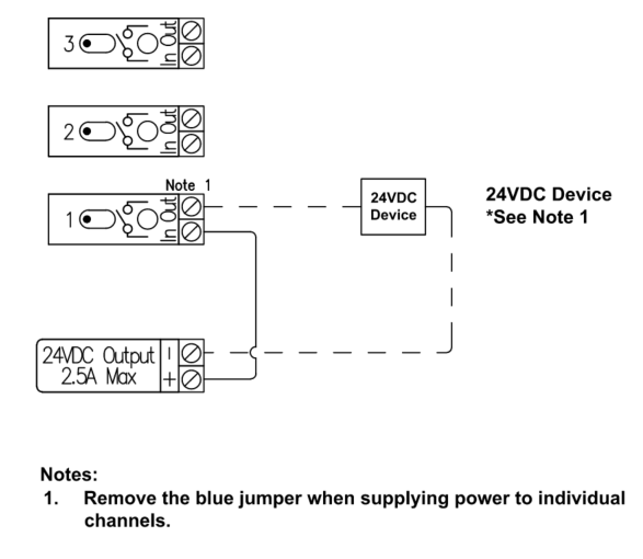
Supplying Onboard 24VDC to Individual SSRs
When you need to provide 24VDC to a device connected to a Steady State Relay Channel and you do not have 24DC supplied to the Power Bus you can connect that relay channel to the Connect Onboard 24VDC output using the following steps.
- Turn all toggle switches of the channels being wired to the "Off" position. This saves the channel fuse from accidentally being blown during device wiring and installation.
- Ensure that each SSR Channel utilizing the 24VDC Power directly has the Jumper Removed.
- Connect the (+) Terminal of the “24VDC Output” to the “IN” Terminal for the SSR Relay.
- Connect the Positive (+) wire of the 24VDC device to the “Out” Terminal of the channel responsible for controlling that device.
- Connect the Negative wire of each 24VDC device sourcing 24VDC power from the relay back to the 24VDC Output (-) Terminal.
Important Note: Only one master Negative wire should be connected to the Connect Controllers 24VDC Output (-) terminal (Max of 12AWG). Use only appropriate external multi-wire connection devices (wire nuts, Wago connectors, terminal blocks, etc.) to connect multiple negative wires together before landing a single negative wire back to the 24VDC Output (-) terminal.
Example Wiring: 24VDC Onboard Output connected directly to SSR Channel 1
Supplying External AC Power Sources (38V Max) to Individual SSRs
There may be a situation where you need to supply a controllable device with a differing AC voltage source or a source with a higher total current output than what is provided with the Connect Onboard 24VAC Output Terminal (2.5A Max). In these cases, you can supply the external voltage directly to the individual channel(s) of the device(s) to accommodate the loads your device(s) require. To do this, follow the steps below:
- Turn all toggle switches of the channels being wired to the "Off" position. This saves the channel fuse from accidentally being blown during device wiring and installation.
- Ensure that each SSR Channel(s) utilizing the External Power Source has its Jumper Removed.
- Connect the Secondary Hot (+) Terminal of the External AC Transformer to the “IN” Terminal for the SSR Relay.
- Connect the “Hot” wire of the AC powered device to the “Out” Terminal of the channel responsible for controlling that device.
- Connect the “Neutral” wire of each AC externally powered device to the Neutral Side of the external AC transformer.
Example Wiring: 24VAC External Transformer connected directly to SSR Channel 1 & 2

Supplying External DC Power Sources to Individual SSRs
There may be a situation where you need to supply a controllable device with a differing DC voltage source or a source with a higher total current output than what is provided with the Connect Onboard 24VDC Output Terminal (5A Max). In these cases, you can supply the external voltage directly to the individual channel(s) of the device(s) to accommodate the loads your device(s) require. To do this you will need to follow the below steps:
- Turn all toggle switches of the channels being wired to the "Off" position. This saves the channel fuse from accidentally being blown during device wiring and installation.
- Ensure that each SSR Channel(s) utilizing the External DC Power Supply has the Jumper removed.
- Connect the Positive (+) Terminal of the External DC power supply to the “IN” Terminal for the SSR Relay.
- Connect the Positive (+) wire of the DC powered device to the “Out” Terminal of the channel responsible for controlling that device.
- Connect the Negative (-) wire of the DC Powered device back to the Negative (-) terminal of the external power supply.
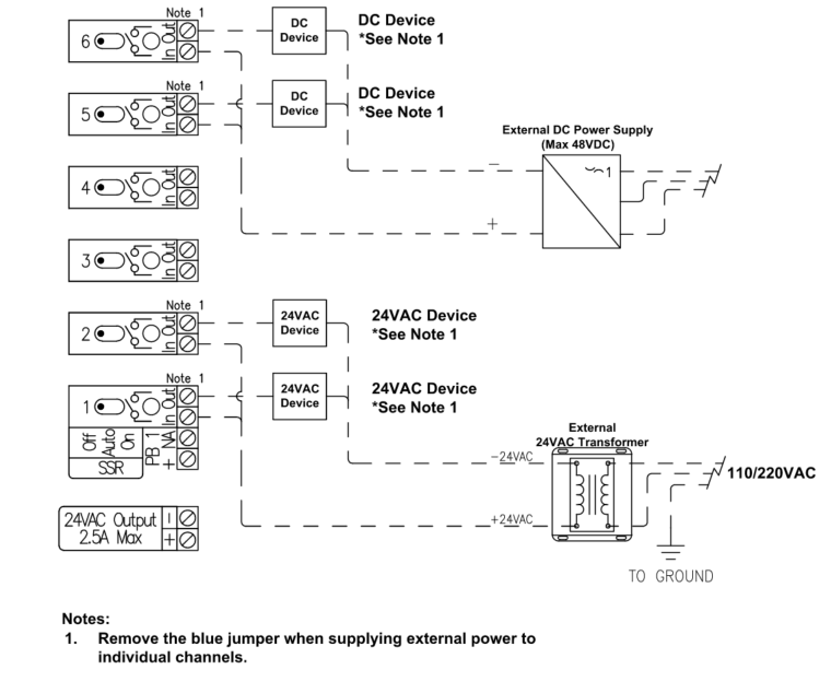
Example Wiring: DC External Power Supply (48V Max) connected directly to SSR Channel 1 & 2
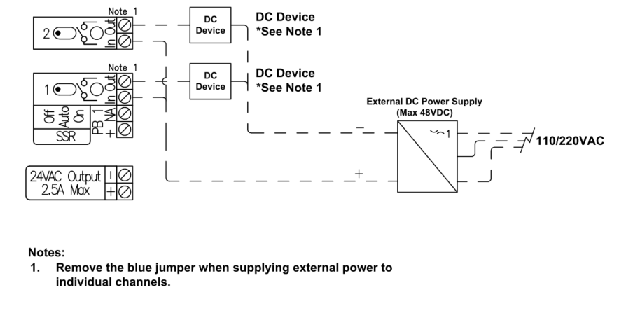
Example Wiring: DC External Power Supply (48V Max) & 24VAC External Transformer connected directly to Individual SSR channels
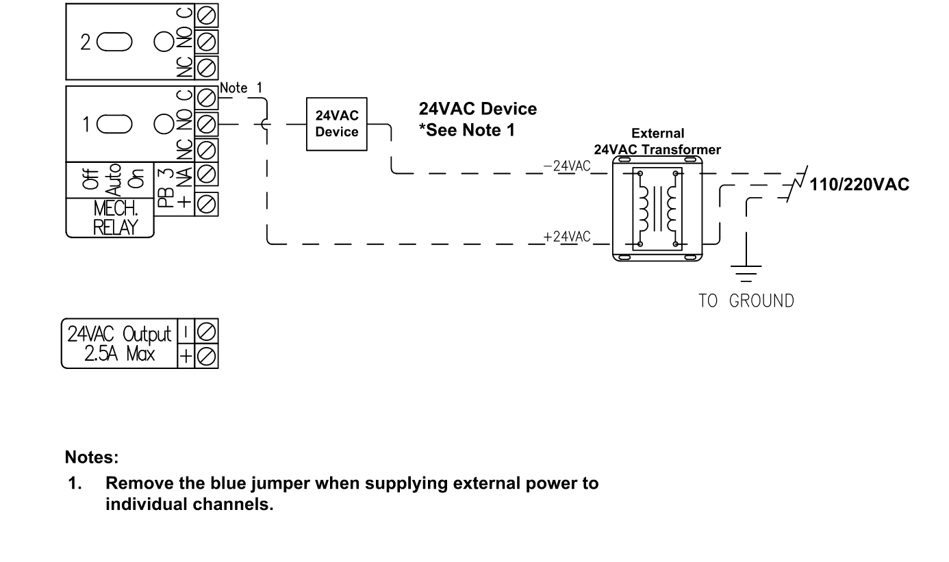
Supplying External AC Power Sources to Individual Mechanical Relays
In situations where a controllable device requires a differing AC voltage source or a source with a higher total current output than what is provided with the Connect Onboard 24VAC Output Terminal (2.5A Max). In these cases, supply the external voltage directly to the individual channel(s) of the device(s) to accommodate the loads the device(s) require. To do this, follow the steps below:
- Turn all toggle switches of the channels being wired to the "Off" position. This saves the channel fuse from accidentally being blown during device wiring and installation.
- Ensure the Mechanical Relay Channel(s) utilizing the External Power Source have the Jumper Removed.
- Connect the Hot (+) Terminal of the External AC Transformer to the “C” Terminal for the SSR Relay.
- Connect the “Hot” wire of the AC powered device to the “NO” Terminal of the channel responsible for controlling that device.
- Connect the “Neutral” wire of each AC externally powered device to the Neutral Side of the external AC transformer.
Example Wiring: 24VAC External Transformer connected directly to Mechanical Channel 1
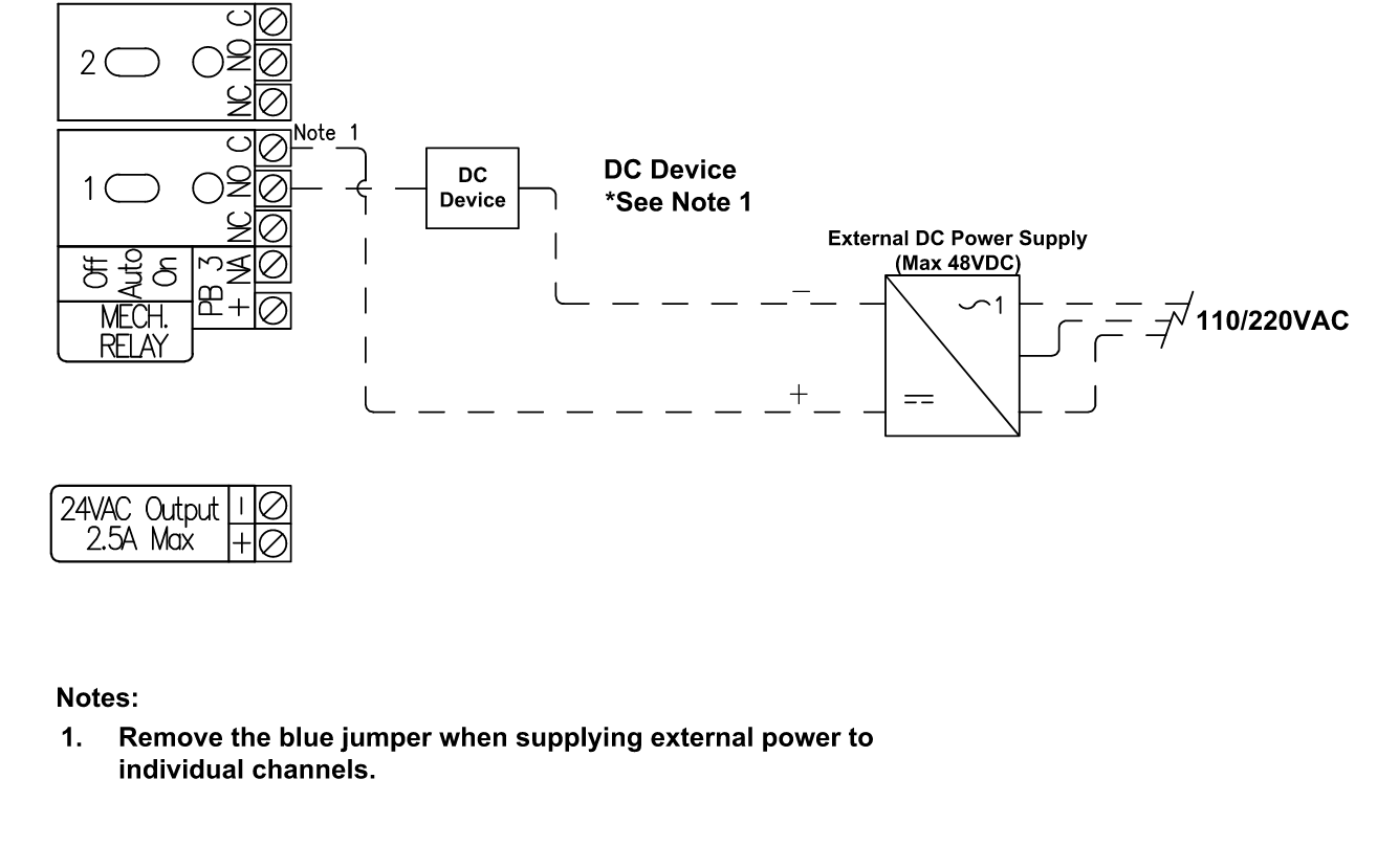
Supplying External DC Power Sources to Individual Mechanical Relays
In situations where a controllable device requires a differing DC voltage source or a source with a higher total current output than what is provided with the Connect Onboard 24VDC Output Terminal (2.5A Max). In these cases, supply the external voltage directly to the individual channel(s) of the device(s) to accommodate the loads the device(s) require. To do this, follow the steps below:
- Turn all toggle switches of the channels being wired to the "Off" position. This saves the channel fuse from accidentally being blown during device wiring and installation.
- Ensure the Mechanical Relay Channel(s) utilizing the External DC Power Supply have the Jumper removed.
- Connect the Positive (+) Terminal of the External DC power supply to the “C” Terminal for the Mechanical Relay.
- Connect the Positive (+) wire of the DC powered device to the “NO” Terminal of the channel responsible for controlling that device.
- Connect the Negative (-) wire of the DC Powered device back to the Negative (-) terminal of the external power supply.
Example Wiring: 24VDC External Power Supply connected directly to Mechanical Channel 1
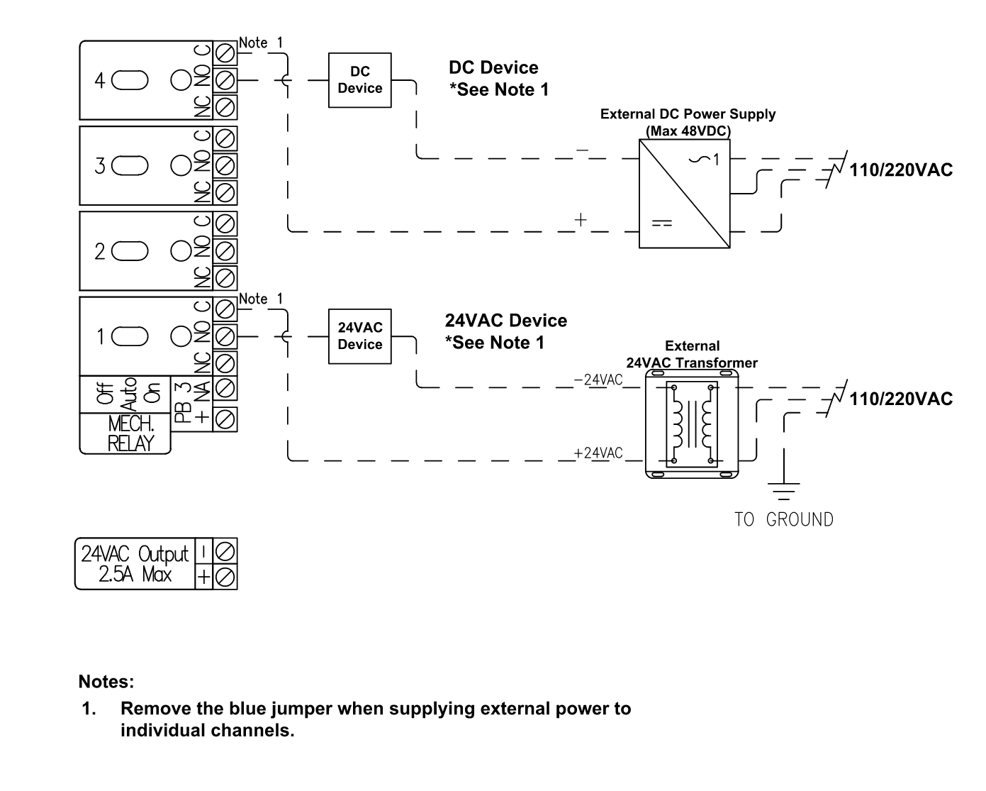
Example Wiring: External AC and DC Power Sources to independent Mechanical Relay Channels
Universal Input Wiring
The Connect Controller has (x8) Universal Inputs that can each connect with and read from any sensor that provides one of the following control signals:
- 0-10V
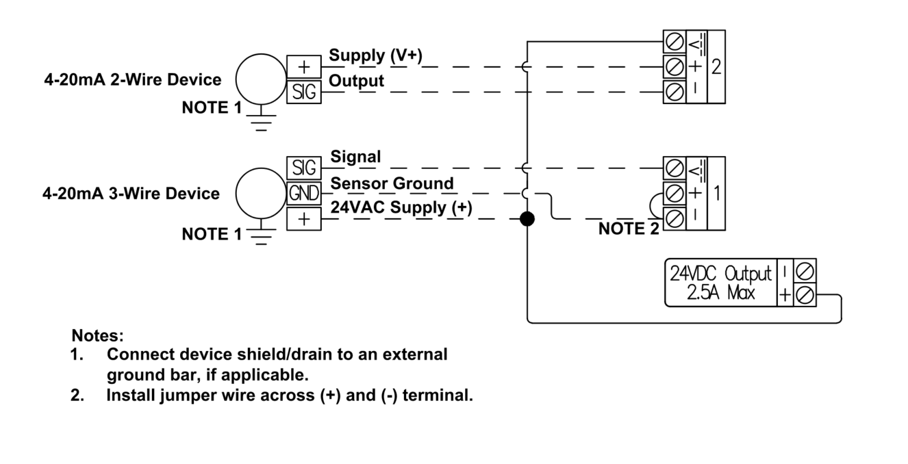
- 4-20mA
- Resistive Input (Range: 760-500k Ω)
- Discrete/Digital Voltage Signals (Digital Inputs)
Common sensors that can be utilized with the Connect Controller are tank level sensors, PAR Sensors, Pressure Sensors, flow sensors, float switches, and any devices having dry contact alarm and/or status output signal options.
WARNING: Never short the "+" and "-" terminals of the Universal Input channel provide while also providing a voltage to the "V" Terminal of the Universal input channel. This may result in damage to your Universal Input Channel.
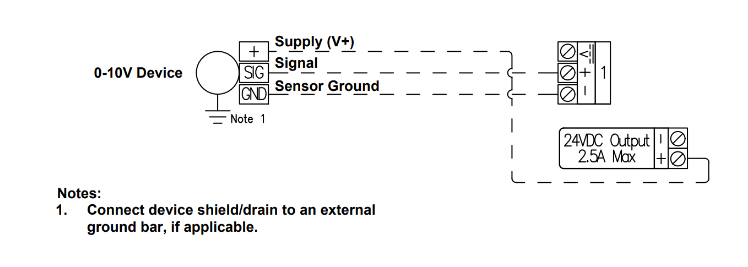
0-10V Wiring Diagram
4-20mA Wiring Diagram
Resistive Input Wiring Diagram

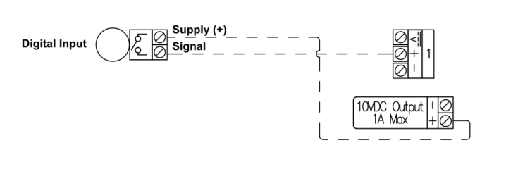
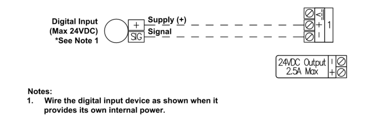
Digital Input Wiring Diagrams
Example: For use with Dry Contacts (Level Switches, Flow Switches, etc.)
Example: Devices that supply a DC output voltage (Max 24VDC) as a Digital Input Signal
Analog Output Wiring
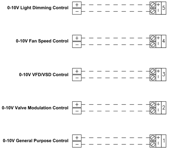
The Connect Controller has (x8) 0-10V Analog Outputs that can be used for providing 0-10V control signals to a variety of devices that accept 0-10V signals. Common controllable devices are light dimming zone control, modulating valves, Variable Frequency Drives (VFD), Variable Speed Drives (VSD), and fan speed control (when fans accommodate 0-10V speed control).
The Connect Controller can accommodate both sinking and sourcing light dimming control and each channel can accommodate up to 200mA of output.
Examples of 0-10V Wiring Output Devices
BACnet MS/TP Wiring
Connecting the Modular 4-in-1 Environmental Sensor Module (ESM-2)
The Connect Controller has a BACnet MS/TP connection that can be utilized for integrating the Growlink Modular 4-in-1 Environmental Sensor Module (ESM-2) to the Controller. For more information about installing and wiring these sensors to your Connect Controller please utilize the diagram and links below:
Spare Output Fuses
Each Connect Controller is shipped with two spare 3.15A fuses for use with the Solid State Relays, and one spare 5A fuse for use with the Mechanical Relays or Power Banks on the Connect. In the event that a fuse gets blown due to a short being induced from downstream field wiring or excess current load, one can swap out the blown fuse on the output with one of the spares. By removing the front face-plate of the connect, one can access the fuses for each Solid State Relay and Mechanical Relay, as well as locate the spare fuses described earlier. The spare fuses are located above the Status LED for the Connect Controller, and each fuse is labeled on the circuit board as 'Spare Fuse'.
The picture below indicates the location of the Spare fuses, where the two 3.15A fuses are outlined in red, and the one 5A fuse is outlined in blue: