ESM -2 Technical Specifications
Click Here To Download The ESM -2 Technical Specifications
Features
• With the Growlink ESM-2, monitor Temperature, Humidity, CO2. VPD.
• Send alerts to smart devices or PC utilizing the Growlink interface.
• Can be used as a general sensor to monitor room conditions or, can be used in conjunction with Growlink environmental control panels.
• Hardwired for dependable communication.
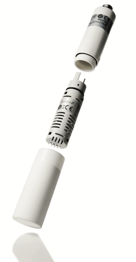
• Sensor filter can be easily removed for cleaning/replacement.
• MSTP communication protocol.
What's In The Box
Note: Each ESM-2 possesses a unique MAC address. The designated room, chain position and MAC address is printed on each ESM-2 box and must be strictly adhered to. MAC addresses for ESM-2s always start at “65”. This is the 1st sensor in the chain and is to be installed at the 1st connector cable in the room closest to the Growlink panel.
- ESM-2
- RS485 Communication Wire
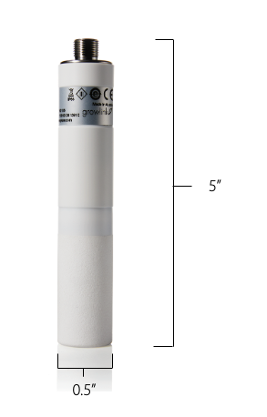
Sensor Dimensions
Installation Guide
Waterproof Junction Box Placement (ESM-2 Hanging Point)
1. Determine optimal sensor placement in space. ESM-2s should be placed evenly throughout the grow space. Ex. If two sensors are assigned, divide the space roughly in half, mount waterproof junction boxes from the ceiling, and hang sensors accordingly.
2. The ESM-2 sensor should be placed at or slightly above the canopy height. For rooms with ceilings of 35 ft. or more, it may be necessary to mount the waterproof junction boxes lower.
3. Join waterproof junction boxes with conduit, or by installing waterproof cable glands in the knockouts.
Power & Signal Cabling
1. Power wiring. The ESM-2 requires 15-30 VDC to operate. This requires running 14 AWG “+” and “-” conductors from the Growlink control panel to each ESM-2.
2. Signal wiring. The ESM-2 requires a twisted shielded pair cable designed for RS485 daisy chains. RS485 24/2 twisted shielded pair should possess an impedance of 100-130 Ω. Growlink recommends using Quabbin Q8302-1 cable or equivalent.
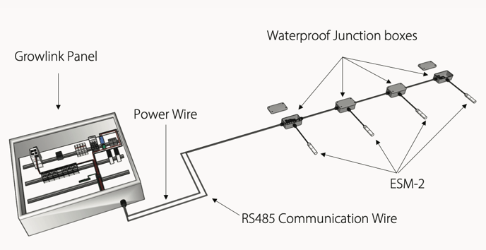
3. Pull both the power cables and RS485 signal cable from the Growlink panel to the closest ESM-2 junction box. From the first junction box, pull the cables to each follow- ing junction box depending on how many ESM-2s are specified for the space. Maintain
a single, continuous daisy chain between all junction boxes.
Note: There should be no star patterns or spider webbing from a central junction box. For an RS485 serial network to operate correctly the chain must be completely linear with no “T-tapping.”
4. Install a waterproof cable gland into the knockout.
5. Insert the provided sensor connector cable through the cable gland.
6. Strip 4 inches of connector cable jacket from the end of the cable.
7. Follow the wiring diagram provided. Make sure to connect the foil and braided cable shields of the RS485 cable which was pulled to the junction boxes.
8. Repeat this process for all junction boxes.
9. IMPORTANT! A 120Ω resistor must be installed between the RS485 “+” and “-“ conductors in the last junction box in the chain. Refer to the wiring diagram for this placement. Make sure this resistor is installed on every RS485 chain in the facility.
10. Terminate both the power and signal cables inside the Growlink panel on the terminal block provided. Refer to wiring diagram and Growlink panel drawings for termination sequence and terminal block location.
Sensor Installation
1. Once all junction boxes are wired per the wiring diagram, install the ESM-2 sensors on the pin connector end of the cable.
2. Make sure the connector end of the cable is at the plant canopy height or expected canopy height. If cable is longer than needed, coil the extra cable and zip-tie it to prevent it from uncoiling.
3. Each ESM-2 possesses a unique MAC address. The designated room, chain position and MAC address is printed on each ESM-2 box and must be strictly adhered to. MAC addresses for ESM-2s always start at “65”. This is the 1st sensor in the chain and is to be installed at the 1st connector cable in the room closest to the Growlink panel.
4. The 2nd ESM-2 with address 66 is to be installed at the 2nd connector cable in the chain. Continue this installation scheme with all remaining sensors in the space if applicable.
5. Sensors are easily connected to the connector cable by aligning the small, notched key on the male threaded pin connector of the ESM-2 with the keyway of the female connector cable end. Once aligned, tighten the threaded collar of the pin connector onto the threads of the ESM-2. If excessive resistance is felt the connector is probably cross-threaded. Do not attempt to tighten further. Loosen the connection, realign and tighten the collar again.
Wiring Diagrams
Click Here To View ESM-2 Wiring Diagrams
Installation Example