Note: The relayLINK must be connected to a LINKS Hub in order to function. 
relayLINK Technical Specifications
|
Input Power |
24Vdc - 1.5A Max. |
|
Max Relay Current |
1A Per Relay |
|
Max Relay Voltage |
24VAC/DC |
| Minimum Cycle Time |
1 Second |
|
Interface |
Hub Connection Port |
|
Terminal Wire Gauge |
26 - 16 AWG |
|
Tightening Torque |
0.3 - 0.4 Nm |
|
DImensions |
4.813"W x 3.5"H x 1.438"D (122mm x 90mm x 36.5mm) |
Features
- 6x 3.5A Dry Contacts: Operate up to eight separate devices independently, ideal for
complex automation setups. - LED Status Indicators: LED lights on the front panel provide real-time status for each relay, making monitoring and troubleshooting straightforward.
What’s Included
x1 relayLINK
x1 Mounting Kit
x1 10 ft. RJ-45 Cable
x1 Mini Screwdriver
relayLINK Dimensions
Size: 4.813" (122mm) W
3.5" (90mm) H
1.438"( 36.5mm) D
Installation & Wiring Instructions
The relayLINK connects to a Growlink HUB and provides 6 individually controllable Dry Contacts for on/off device control.
relayLINKs are intended for:
- HVAC Relays (Requires HUB, canopyLINK, Climalink, and Lighting Control via 4 Channel or digital lightLINK)
- Dehumidifier Control (For units with low voltage external control options.)
- Humidifier Control (For units with low voltage external control options.)
- Miscellaneous dry contact on/off control

Setup Button: Readdresses the relayLINK module.
Relay LED Status Indicators (x6): Displays dry contact relay activity.
Dry Contact Terminal Relays (1-6): Terminal connector for dry contact relays.
HUB Connection Port: RJ-45 connector port for power & data.
HUB LED Status Indicator: Indicates device power and HUB communication status.
relayLINK Outputs (Dry Contacts)
Dry-contact relays consist of a mechanical switch (contact) and an electromagnet
that closes the contact when energized. A spring reopens the switch when power is
removed. The contact operates similarly to a wall switch, physically connecting two
screw terminals. Dry contacts are commonly used to switch low-voltage AC control
signals, such as those for HVAC units and irrigation solenoids.
1. Irrigation Solenoid Valves
24VAC irrigation and gas valves can be controlled by switching power supplied by a step-down transformer. 24VAC is safer and more common than line-voltage for water/irrigation solenoids.
2. A.C. Coil Relays & Contactors
Contactors and relays with 24VAC coils can be operated by controlling the power from a transformer to the magnet coil with a dry contact switch.
relayLINK Outputs (HVAC Control)
Dry contacts are required to switch the AC control voltage in HVAC and commercial
dehumidifier units. HVAC units typically supply 24VAC from a built-in control
transformer located in the HVAC unit. The 24VAC supplied by the Unit is switched to the
various control signal wires allowing voltage to return to the unit, activating the
appropriate component (i.e., Fan, Cooling, Heating, etc.). Do not split the control of a
single HVAC unit between multiple relayLINKs (i.e. do NOT jumper 24V (R) from a single
HVAC unit between two different relayLINK devices).
1. HVAC
Typical example of connections to a RTU (roof top unit) HVAC system or other Air Handling Unit or Fan Coil Unit that is controlled with on/off relays.
2. Humidifiers & Dehumidifiers
Commercial humidifiers and dehumidifiers typically provide both an economical internal humidistat control and terminals for external humidistat control. Contact your equipment manufacturer or review your equipment installation manual for details on which connections to make for dry-contact external control.
Anden® dehumidifier units can be connected to a low-voltage dry contact for external
control. Multiple units can be daisy-chained together as shown in the diagram below.
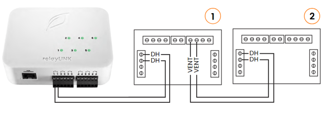
- Connect the “VENT” contacts of Unit #1 to the“DH” contacts of Unit #2.
- Refer to Anden® operation manual for additional setup instructions
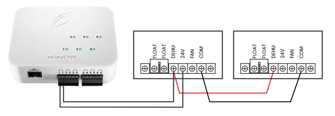
relayLINK Outputs (Quest® Dehumidifiers)
Quest® dehumidifier units can be connected to a low-voltage dry contact for external
control. You may control up to four Quest® units with a dry contact by wiring all
Common (COM) terminals and DEHU Terminals together.
Note: If you don’t see a component in the wiring diagram that matches your brand of HVAC system, humidifier, dehumidifier, or other mixed-voltage equipment, contact the manufacturer.
More detailed Installation instructions can be found by referencing the following manual:
relayLINK Instruction Manual
Mobile App Setup Guide
1) Plug in your Growlink device to power it on. The LED should be blinking blue. If not, hold the SETUP button until status light flashes blue rapidly (12-15 seconds).
2) Download the Growlink app from the Apple App Store, or Google Play Store. 
3) Go to portal2.growlink.com/signup or tap the ‘Sign Up’ button at the login page of the Growlink Mobile App to create a Growlink Account:

After creating your account, a verification email will be sent from ‘no-reply@growlink.com’ to the email address set for your newly created account. One must verify your email address in order to utilize your newly created account.
4) Open the Growlink Mobile App and login to your newly created and verified account:
5) Tap the icon of three lines in the top-left of the Mobile App, then tap the Hardware button in the following menu:
6) One can add a controller to an existing room, or tap the ‘+Add’ button in the following page to add a new room to your account. This is the container that will hold the future controller registration:
7) If you are creating a new Room, provide a name for the Room, the Square Footage of the Room, and the Room Type, followed by tapping the 'Create’ Button to finish creating that room:
8) Once an existing room has been selected or a new room has been created, tap the ‘Continue’ button to begin registering the controller to your account.
9) In the Add Hardware Wizard, tap the LINKS button in the following page:
10) Select the ‘Add Devices’ option to add the controller to the specified room:
11) Select the ‘relayLINK’ option in the following menu that populates:
12) A relayLINK cannot be setup as a standalone controller and instead must be connected to a LINKS Hub. In the following screen, select the LINKS Hub you wish to connect the relayLINK to:
Connect the relayLINK to one of the Hub ports on your LINKS Hub in order for the relayLINK to be detected by your LINKS Hub.
13) Once the relayLINK has been detected, the app will populate outputs of the relayLINK, where you can then name the outputs, set the device types for those outputs, and register that configuration to your LINKS Hub:
14) Once the outputs have been named to your liking and any required fields for the module have been designated, one can tap the ‘Register Device’ to push that configuration to your newly configured relayLINK and paired LINKS Hub.
15) Once successfully connected and configured, the following success message will display. Tap the ‘Add Equipment to this Controller’ to add more hardware to the associated LINKS Hub, Tap the ‘Edit Controller Profile’ button to update the Controller Profile Settings, or tap the ‘Go to Room Dashboard’ button to view the dashboard for the newly connected controller:
Troubleshooting
Controller not showing up on my list of devices to connect:
Check your phone or tablet and ensure Bluetooth is enabled.
Hold down the Setup button located on the controller (see image below) for approximately 12-15 seconds until there is a rapid flashing blue light. Then refresh the device list on your phone or tablet.
Unplug the unit for 10 seconds and then plug the device back in and wait for the LED lights to stop changing colors (typically 15 seconds). Then refresh the device list on your phone or tablet.
Controller didn’t connect to Wi-Fi:
If unsuccessful in the first attempt to connect the controller to the Wi-Fi network, hold down the Setup button located on the controller (see image below) for approximately 12-15 seconds until there is a rapid flashing blue light. Once rapid flashing becomes visible, immediately release the Setup button. This will put the controller into Listening Mode (Blinking Blue). Now, restart the connection process outlined in the Quick Setup Guide section above.
The Wi-Fi network being used has changed:
In the event the controller needs to re-connect to an existing or new Wi-Fi network, put the controller back into Listening Mode (see above) and follow the Controller Connection process outlined in the Quick Setup Guide section above.
Controller LED Status Light Color Codes
During device setup and operation, these are the LED light indicators:
- Solid White: Firmware Startup
- Slow Flashing Green: Wi-Fi connecting
- Fast Flashing Green: Wi-Fi waiting on IP address
- Fast Flashing Cyan: Wi-Fi connected, connecting to cloud
- Fast Breathing Green: Loading configuration and detecting probes
- Slow Breathing Green: Connected to cloud and running
- Slow Flashing Blue: Wi-Fi configuration mode
- Safe Mode: Slow breathing magenta
- Safe Mode Requested: Fast flashing magenta
- Firmware Updating: Slow flashing magenta
- Slow Flashing Blue: Wi-Fi setup mode
