Setup Instructions for Crop Steering & Substrate Monitoring Equipment
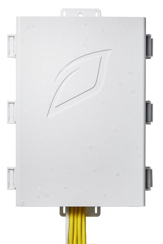
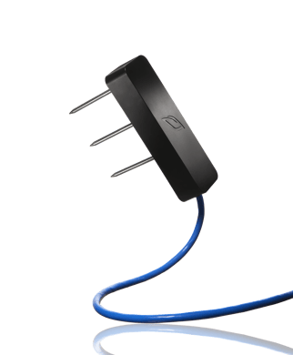
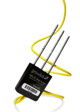
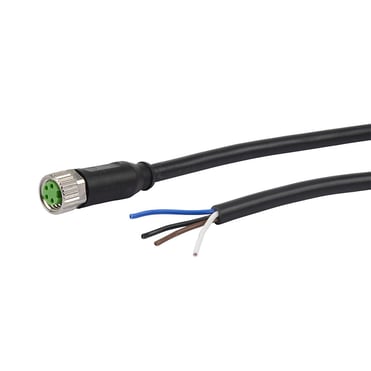
Table of Contents
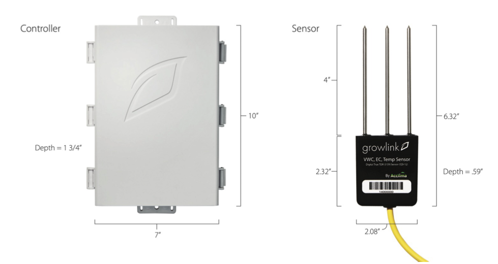
- Precision Irrigation Controller Technical Specifications
- Features
- What's In the Box
- Controller Installation
- Terralink Sensor Installation
- TEROS 12 Sensor with Adapter Cable Installation
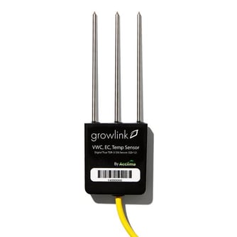
- TDR Sensor Installation
- Sensor Placement
- Mobile App Setup Guide
- Irrigation With Crop Steering
- Setting Simple Timers, Schedules and Sensor Triggers in the Growlink Mobile App
- Troubleshooting
Precision Irrigation Controller Technical Specifications
| Power: | 24VAC or 24VDC (v11 and newer) using provided power supply |
| SDI-12 Sensor Input(s): | 12 VDC Power |
| 3.3v Signal | |
| Output: | 4x 24 VAC / 1A Fused |
| Ethernet (available on PIC v11 and later) |
CAT5e or CAT6 |
| Wi-Fi | 2.4 GHz |
Features
Remote Access - Manage and monitor your climate and substrate remotely and quickly adjust strategies from a smartphone, tablet, or laptop - anytime, anywhere.
Multi-Sensor Compatablity - The PIC may currently be used with Growlink Terralink, Acclima TDR or Meter Group TEROS 12 (with the appropriate adapter cable), providing the ultimate choice to use the sensor you like best.
Substrate Selection – The Precision Irrigation Controller can be configured to accurately measure and report using several types of growing substrates.
OTA Updates - Our controllers regularly receive over-the-air software updates that add new features and enhance existing ones over Wi-Fi or ethernet.
Alerts - Stay informed on all active and historical alerts from your Growlink systems via email, text or push notifications through the Growlink Mobile App (if push notifications are enabled on your device).
Fanatical Support - Free support from a Growlink specialist (during office hours).
What’s In The Box
1x 24V Power Supply
1x Mounting Hardware Kit
Varying quantity of Substrate Sensors based on order.
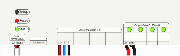
Controller Installation
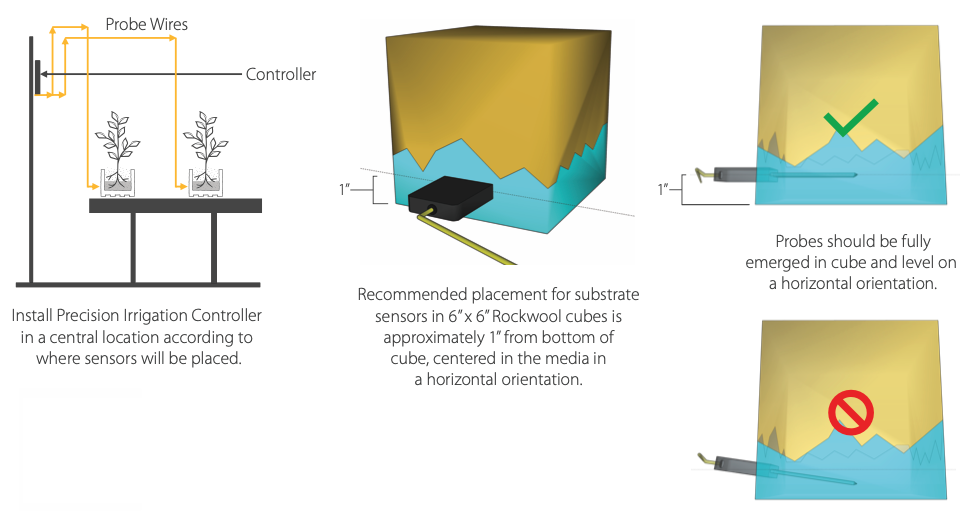
- Mount the PIC to a solid vertical surface such as a wall or vertical rack structure which is located as centrally as possible to where the sensors will be installed. Use the provided hardware mounting kit or suitable hardware for your mounting surface and attach the PIC to the surface using the mounting tabs located on the top and bottom of the controller's enclosure.
- Connect the provided power adapter to the 'Power' terminal located on the Irrigation control board inside the enclosure.
- Plug the power adapter into an appropriately rated receptacle for your country using the correct adapter prongs provided.
- If a hardwired internet connection is desired and the PIC has an ethernet port (older versions do not have an ethernet port), connect a CAT5e or CAT6 cable with an RJ45 terminated on the cable end to the PIC ethernet port. Connect the other end to your internet router or network switch directly. Do not connect this cable to a booster or wireless adapter.
- Important: Do not connect this ethernet cable to a PoE (Power over Ethernet) port on a network switch. The PIC does not need PoE.
Terralink Sensor Installation
Find generic wiring diagram examples for both multiple and single Terralinks per channel here.
Single Terralink per PIC Channel Installation
- The Terralinks are connected directly to the zone terminals of the PIC indicated in the provided wiring diagram (see Terralink Wiring Diagrams link above). If multiple sensors will be used per zone, proceed to the next section for daisy chaining instructions.
- Strip the wire insulation off the cable ends and insert each color wire in the appropriate terminals of the PIC as indicated on the wiring diagram. *Note: If the cable needs to be extended to reach the PIC, you may extend this cable with 18AWG (1mm) / 3 Conductor cable. The total cable length, including the provided cable attached to the sensor, should not exceed 175' (53.3m).
-
- Red wire to '12V' Terminal
- White wire to 'S' Terminal
- Silver (bare) wire to 'G' Terminal
-
- Use a small flat blade screwdriver (3/32”) to hand tighten all 3 screw terminals on to the copper wire. Once tightened, gently pull on each wire to ensure they are fully secured in the terminal. If any slip out, repeat the above steps. IMPORTANT: Make sure there is not any copper exposed outside of the terminals. This may lead to two conductors contacting and short circuiting the sensor.
- Repeat for the remaining Terralink sensors.
Multiple Terralink per channel Installation (Daisy Chaining in Commercial Applications)
*IMPORTANT: Daisy chaining sensors requires the Precision Irrigation Controller be paired with a Core controller or IoT Gateway. Daisy chaining is not possible with standalone PICs.
- If more than 1 Terralink sensor is intended to be used per zone, making multiple connections with waterproof junction boxes or T-connectors must be utilized. A single junction box or daisy chain configuration may be used. Consult the example installation video and generic wiring diagrams for further installation details.
- IMPORTANT: A maximum of 10 Terralink sensors with unique addresses may be installed on a single zone chain. Duplicate addresses on the same chain are not compatible. Available addresses are 0,1,2,3,4,5,6,7,8 & 9.
- IMPORTANT: The total length of the daisy chain must not exceed 175ft (53.3m) from the PIC at the furthest point. Exceeding this distance may lead to unreliable data transmission.
- For each zone, run an 18/3 AWG (1mm) copper home-run cable to the 1st junction box from the PIC controller. From this point, either run 18/3 AWG wire to each subsequent junction box or directly connect Terralink sensors in the junction box.
- Verify each Terralink sensor address is unique within each zone chain. The address on each sensor must be unique on a single PIC input channel. Each input can support one of each sensor address (0-9) and the PIC has 4 inputs for a maximum total of 40 sensors per PIC.
- Strip individual conductors to expose copper then make connections using either Wago connectors, wire nuts or a similar secure wire connection method. Follow the provided wiring diagram for all connections. Make sure to keep wire color and polarity consistent throughout the entire chain.
- Insert each color wire in the appropriate terminals of the PIC as indicated on the wiring diagram (see 'Terralink Wiring Diagrams' link above). Then use a small flat blade screwdriver (3/32”) to hand tighten all 3 screw terminals. Once tightened, gently pull on each wire to ensure they are fully secured in the terminal.
- Repeat these steps for additional Terralink daisy chain zones.
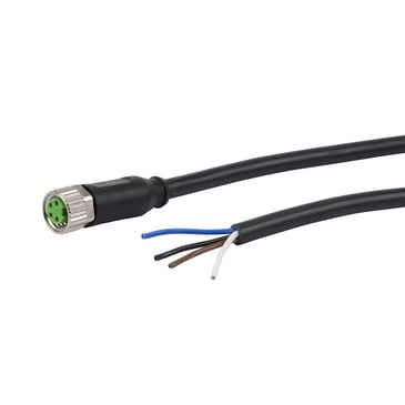
TEROS 12 Sensor with Adapter Cable Installation
Single TEROS 12 per PIC Channel Installation
- The TEROS 12 is connected directly to the zone terminals of the PIC using adapter cables purchased from Growlink.
- Align the pins of the TEROS 12 sensor cable with the adapter cable end. Connect the two ends and hand tighten the threaded barrel connector.
- Strip the wire insulation off the adapter cable end and insert each color wire in the appropriate terminals of the PIC as indicated below. *Note: If the cable needs to be extended to reach the PIC, you may extend this cable with 18AWG (1mm) / 3 Conductor cable. The total cable length, including the provided cable attached to the sensor, should not exceed 175' (53.3m).
-
- Brown wire to '12V' Terminal
- White wire to 'S' Terminal
- Blue wire to 'G' Terminal
-
- Use a small flat blade screwdriver (3/32” works best) to hand tighten all 3 screw terminals on to the copper wire. Once tightened, gently pull on each wire to ensure they are fully secured in the terminal. If any slip out, repeat the above steps. IMPORTANT: Make sure there is not any copper exposed outside of the terminals. This may lead to two conductors contacting and short circuiting the sensor.
- Repeat for the remaining TEROS 12 sensors.
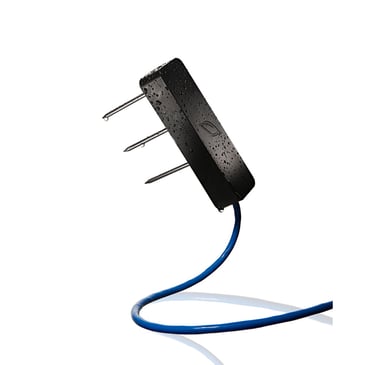
TDR Sensor Installation
Find generic wiring diagram examples for both multiple and single TDRs per channel here.
Single TDR per Channel Installation
- The TDR probes are connected directly to the zone terminals of the PIC indicated in the provided wiring diagram (see TDR Wiring Diagrams link above). If multiple TDR probes will be used per zone, proceed to the next section for daisy chaining instructions.
- Strip the wire insulation off the cable end and insert each color wire in the appropriate terminals of the PIC as indicated on the wiring diagram. *Note: If the cable needs to be extended to reach the PIC, you may extend this cable with 18AWG (1mm) / 3 Conductor cable. The total cable length, including the provided cable attached to the sensor, should not exceed 175' (53.3m).
-
- Red wire to '12V' Terminal
- Blue wire to 'S' Terminal
- White wire to 'G' Terminal
-
- Use a small flat blade screwdriver (3/32”) to hand tighten all 3 screw terminals on to the copper wire. Once tightened, gently pull on each wire to ensure they are fully secured in the terminal. If any slip out, repeat the above steps. IMPORTANT: Make sure there is not any copper exposed outside of the terminals. This may lead to two conductors contacting and short circuiting the sensor.
- Repeat for the remaining TDR sensors.
Multiple TDR per channel Installation (Daisy Chaining in Commercial Applications)
*IMPORTANT: Daisy chaining sensors requires the Precision Irrigation Controller be paired with a Core controller or IoT Gateway. Daisy chaining is not possible with standalone PICs.
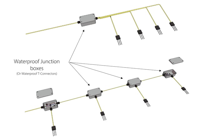
- If more than 1 TDR sensor is intended to be used per zone, making multiple connections with waterproof junction boxes or T-connectors must be utilized. A single junction box or daisy chain configuration may be used. Consult the example installation video and generic wiring diagrams for further installation details.
- IMPORTANT: A maximum of 10 TDR sensors with unique addresses may be installed on a single zone chain. Duplicate addresses on the same chain are not compatible. Available addresses are 0,1,2,3,4,5,6,7,8 & 9.
- IMPORTANT: The total length of the daisy chain must not exceed 175ft (53.3m) from the PIC at the furthest point. Exceeding this distance may lead to unreliable data transmission.
- For each zone, run an 18/3 AWG (1mm) copper home-run cable to the 1st junction box from the PIC controller. From this point, either run 18/3 AWG wire to each subsequent junction box or directly connect TDR sensors in the junction box.
- Verify each TDR sensor address is unique within each zone chain. The address on each sensor must be unique on a single PIC input channel. Each input can support one of each sensor address (0-9) and the PIC has 4 inputs for a maximum total of 40 sensors per PIC.
- To find the address of each sensor, reference the images below.
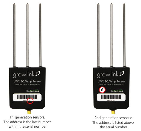
- To find the address of each sensor, reference the images below.
- Strip individual conductors to expose copper then make connections using either Wago connectors, wire nuts or a similar secure wire connection method. Follow the provided wiring diagram for all connections. Make sure to keep wire color and polarity consistent throughout the entire chain.
- Insert each color wire in the appropriate terminals of the PIC as indicated on the wiring diagram (see 'TDR Wiring Diagram' link above). Then use a small flat blade screwdriver (3/32”) to hand tighten all 3 screw terminals. Once tightened, gently pull on each wire to ensure they are fully secured in the terminal.
- Repeat these steps for additional TDR daisy chain zones.
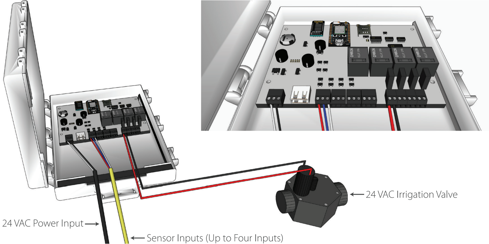
Solenoid Valve Wiring
Up to 4 24VAC solenoid valves can be connected to and controlled by the Precision Irrigation Controller. The solenoids must be 24VAC to operate with the PIC. Any other voltage is not compatible with the outputs.
Each solenoid must be ran directly to each output, and one cannot combine neutral wires of multiple outputs together. Doing so can irreversibly damage the outputs on the PIC.
- Connect the solenoid valve wires to the 4 labeled outputs on the right side of the PIC control board. The wire orientation should not matter with 24VAC valves.
Sensor Placement

Mobile App Setup Guide
- Plug in your Growlink device to power it on. The LED should be blinking blue. If not, hold the SETUP button until status light flashes blue rapidly (12-15 seconds).
- Download the Growlink app from the Apple App Store, or Google Play Store.

- Open the Growlink app and tap Create Account.
- After creating an account, log into the app.
- Tap on the settings icon in the top right corner and then tap Connect a Controller. If it is your first time creating an account, you will be automatically prompted to Setup A New Device.
NOTE: The first time using the Growlink app you will be prompted to allow Bluetooth access. This is required to setup newer Growlink controllers.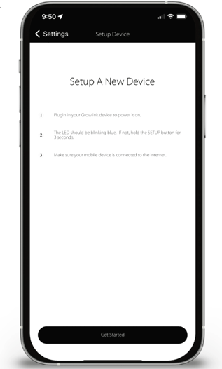
- Connect the controller to internet. Watch the video or follow the instructions below to learn how.
- For iPhone users:
- If controller has a Bluetooth logo printed on it, tap New Bluetooth Device, then tap on the controller you wish to connect to from the list. A successful connection will be indicated with a "Congrats" message.
- If using a Legacy model controller (Non-Bluetooth), tap "Legacy Wi-Fi Device". From the "Waiting for Wi-Fi connection" screen, follow the instructions shown on your device to complete the Wi-Fi connection process.
- For Android users: The Growlink app will detect if your controller is a Bluetooth device or a Legacy model device. Simply tap on the controller you wish to connect to once it shows on the screen.
- For iPhone users:
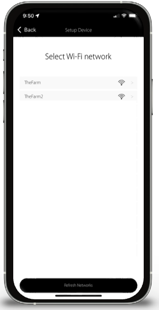
- After the connection process is complete, a list of available Wi-Fi networks will appear. Tap on the network you wish to connect the controller to, enter the network password, then tap Next.
- Name your controller (i.e. Flower Room Irrigation). Tap Register Controller.
- After controller registration, tap on Go To Settings.
From the Controller Profile page, you can set where you are located, time zone, Day Start & Day End (Lights On and Lights Off). After making changes, tap Save and you will be returned to the Main Dashboard.
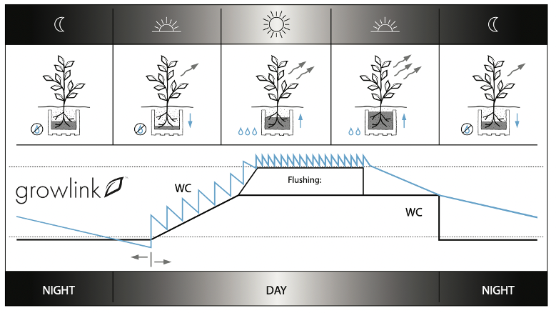
Irrigation with Crop Steering
Learn more about Growlink's advanced, AI driven crop steering programs called Copilot and Autopilot here:
Growlink Copilot Crop Steering Guide
A Growlink Pro subscription is required to access advanced features like Copilot and Autopilot by utilizing the Growlink Web Portal. See subscription pricing and features here: Growlink Controls Software
To receive a complete guide on what Crop Steering is, visit this link scroll to the bottom of the page and enter your e-mail to receive our free e-book.
Setting Simple Timers, Schedules and Sensor Triggers in the Growlink Mobile App
The Growlink Mobile App is always free to download from your app store. It includes the ability to set up basic timers, schedules and sensor trigger automations. See this video for a general explanation on how rules are programmed through the mobile app.
If you use or intend to use Copilot and Autopilot crop steering programs, you do not need to set up simple timers, schedule or sensor triggers. The crop steering program manages these rules for you.
Troubleshooting
Sensor readings not showing up on all inputs OR input ports were moved from original placement: If you are not seeing all sensors showing up on the Dashboard or are seeing incorrect readings after moving input terminals, press the Reset button located on the front of the controller.
Controller didn't connect to Wi-Fi: If you are unsuccessful in the first attempt to connect your controller to a Wi-Fi network, hold down the Setup button located on the front of the controller for approximately 12-15 seconds until you see a rapid flashing blue light. Once you see the rapid flash, immediately release the Setup button. This will put the controller into Listening Mode (Blinking Blue), and you will then restart the connection process outlined in step 4 of this guide.
The Wi-Fi network or password has changed: In the event you need to re-connect the controller to a Wi-Fi network, put the controller back into Listening Mode (see above) and follow the Controller Connection process outlined in step 4.
Controller LED Status Light Color Codes
During device setup and operation, these are the LED light indicators:
- Solid White: Firmware Startup
- Slow Flashing Green: Wi-Fi connecting
- Fast Flashing Green: Wi-Fi waiting on IP address
- Fast Flashing Cyan: Wi-Fi connected, connecting to cloud
- Fast Breathing Green: Loading configuration and detecting probes
- Slow Breathing Green: Connected to cloud and running
- Slow Flashing Blue: Wi-Fi configuration mode
- Safe Mode: Slow breathing magenta
- Safe Mode Requested: Fast flashing magenta
- Firmware Updating: Slow flashing magenta
- Slow Flashing Blue: Wi-Fi setup mode