Troubleshooting Guide – Metz Modules
Metz modules are modular hardware that are used to control relays, dimming zones, and pumps. Each Metz Module communicates over BACnet MS/TP and can be chained together in order to control a wide variety of devices from a single controller. Listed below are the different types of Metz Modules used within our panels and some troubleshooting steps one can take in order to isolate potential issues with BACnet MS/TP communications.
Digital Output Module (DO-4)
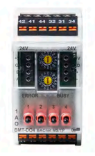
The Digital Output Module has 4 relays that can be configured as wet contacts or dry contacts in order to control downstream devices. Common use cases include irrigation valves as wet contacts, and dehumidifiers, contactor banks for lights, and cooling/heating stages for HVAC units as dry contacts. One can manually engage or disengage each relay by using the black toggle switches for each output. A is Auto and allows our software to command the output, 1 turns on the relay, and 0 turns off the relay.
Analog Output Module (AOP-4)
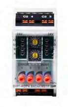
The Analog Output Module is used to send a 0-10VDC signal towards a downstream field device. These modules have 4 red dials that function as potentiometers, which allow one to manually set a control voltage being sent by rotating the red dial, or allow one to keep them in Auto (A) to be controlled via our software interface.
The most common use case for these modules is to send dimming control voltage towards lights in order to control their brightness. The AOP-4 is used in conjunction with an Analog Buffer Board to allow one to use a higher control voltage of 0-12VDC if needed with particular manufacturers of lights that utilize an ‘Overdrive’ setting.
Triac Output Module (TO-4)
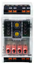
The Triac Output Module is similar to a DO-4 in that there are 4 relays on each Triac Output Module, but has a higher cycle rate. A Triac Output Module is utilized to control pumps such as HE Anderson pumps, as the relays turn on rhythmically in order to fire the pumps at the desired injection rate. Similar to the DO-4, one can use the black toggle switches to manually engage the relay, where keeping the toggle switch on A allows our software to command the output, 1 manually engages the relay, and 0 manually disengages the relay.
Analog Input Module (CI-4)
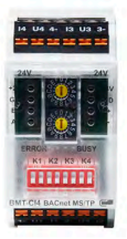
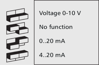
The Analog Input Module is utilized to read a voltage input from a device in the field, and is capable of detecting 0-20mA, 4-20mA, and 0-10VDC signals depending on the position of the dip switch position used on each input. Each input has two dipswitches that can be toggled up or down depending on the type of sensor being connected. More information regarding the dip switch position and its corresponding function for CI-4’s can be determined by referencing the picture above.
Pulse Counter Module (SI-4)
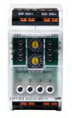
The Pulse Counter Module is utilized to convert the pulses generated from a flow meter into a Gallons Per Minute (GPM) flow rate, which is then utilized by our software to control pumps based on the desired injection volume designated for the pumps.
Common steps to take when troubleshooting Metz Modules are as follows:
There are no lights visible on the Metz Modules
Every Metz Module has a number of LED’s, an Error LED (Red/Green), a Busy LED (yellow), and an LED for each output on the Metz Module (Yellow). If no LED is visible on the Metz module, then it is likely that the Metz Module does not have power. A Metz module requires 24VDC in order to power on and communicate across the MS/TP chain. Checking the power terminal blocks (+24V and G) with a multimeter can help confirm if the Metz module has power or not:
A Red ‘Error’ Light is illuminated and does not disappear
Intermittent Flashes of a Red error light are normal for an MS/TP chain, as it is indicating a garbled message across the chain. However, if the Red ‘Error’ LED on the Metz module stays illuminated and does not disappear for longer than 30 seconds, there is likely an issue with either communication across the MS/TP chain or the Metz Module itself.
If an MS/TP device has recently been added to the chain, the issue is likely that the new device or sensor has a duplicate address with another sensor or device within the chain, or that the added device has not had its Baud Rate and MAC Address Set.
Following the steps in the video below can help confirm that the Baud Rate and MAC Address has been set on the Metz Modules appropriately (more videos like this one can be found at our Growlink University Webpage):
If the Red Error LED is still persisting after it has been confirmed that the Metz modules are set to the appropriate Baud Rate and MAC Address, then the next steps are to check the signal wiring across the MS/TP chain to ensure there is not a loss of communication across the chain due to a loose signal wire.
Lastly, in some rare cases a power surge or incorrect field wiring can damage the Metz modules themselves. Bypassing the suspected failed Metz Module can help isolate the loss of communication across the MS/TP chain and restore communication to the other modules within the chain. The left and Right side of the Metz module has a 4 pin terminal block that can be unplugged by pulling the terminal block towards you. By removing the terminal block and connecting the same terminal block to the next module within the chain, one can bypass the suspected bad Metz module to further isolate communication issues across the chain.
The Output LED’s (Yellow) do not illuminate when commanded on from the Growlink Dashboard
If one commands an output on from the Growlink Dashboard and the corresponding output does not illuminate within the panel, this may signal an MS/TP comms issue due to a loose signal wire or a Metz Module that has not had its Baud Rate or MAC Address set appropriately.
One can confirm that the Baud Rate and MAC Address for the Metz modules are set correctly by referencing the video above.
Once this has been done, reboot the controller the Metz modules are connected to. If no lights are still illuminated when commanding the output on, check the signal wires across the MS/TP chain. If no loose signal wires are found, reach out to our Support team at Support@Growlink.com in order to have our team investigate what is being seen by the controller when attempting to communicate to the sensors and devices within the current MS/TP chain.
Commands given take ~30 seconds or more to execute
If there is a lag-time between a command being given to the Metz modules within the MS/TP chain and the actual relay engaging, the most common cause of this increase in latency is a loose signal wire. One will want to check each connection across the chain and ensure that there is not a loose signal wire or bridge connection. If one lightly pushes on each terminal block and bridge connection, one can quickly check to confirm there is not a loose connection that is resulting in the increase in latency seen.
Analog Input reading -2.3% and not changing from that value
An Metz Analog Input Module (CI-4) will only read -2.3% if the current loop setup is open, meaning that there is a <4mA signal currently being recorded by the module. The most common cause of this behavior is a loose or incorrect wiring termination affecting the current loop itself.
Analog Input reading 105% and not changing from that value
A Metz Analog Input Module (CI-4) will only read 105% if there is voltage being back-fed to the Metz CI-4, meaning that there is a >20mA signal currently being recorded by the module. The most common cause of this behavior is an incorrect wiring termination or damaged sensor that is back-feeding voltage towards the signal input in the current loop. Checking wiring terminations and isolating the wiring issue will resolve this issue. If the Input still reads 105% with no downstream wires connected, then the Metz CI-4 has been damaged from the back-fed voltage and must be replaced.
Warranty Info:
Metz Modules have a manufacturer warranty of 1 year from the date of receipt or date of registration by the customer, whichever occurs first. Further warranty information can be found at the link below:
https://www.growlink.ag/return-policy-1