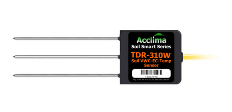
Acclima Probes emit a wavelength into the substrate, then compare the emitted wave to what is reflected back in order to calculate the water content and EC of a given substrate. Appropriate substrate placement and common issues seen with substrate probes are listed below as well as steps one can take to isolate and resolve them:
Acclima Substrate Placement
For Rockwool cubes and slabs, appropriate placement is 1” from the bottom of the substrate. If one is using a rockwool slab, one would want to place the substrate probe equidistant between two plants within that slab.
For CoCo substrates, the placement differs with the size of the pot being used. For 1 gallon CoCo pots, 1” from the bottom is the appropriate placement. For 2 gallon CoCo pots, 2” from the bottom will suffice. For 3 gallon CoCo pots and larger, 3” from the bottom is the appropriate placement.
Sensor reading 100% VWC
Because the sensor is sending out wavelengths and comparing what was emitted to what is reflected back, having solid contact between the substrate and the sensor is paramount to receiving a stable reading of both moisture content and EC. If a sensor is reading an extremely high VWC reading such as 100% while placed within the substrate, the likely cause is an air pocket that has formed around the tines of the probe that has since filled with water. By placing the probe on the other side of the same substrate, one can gauge if the issue is due to a poor fit between the sensor and the substrate or if the issue lies with the sensor itself.
Sensor reading 0% VWC
Similar to the section outlined above, if an air pocket forms around the tines of the probe and does not fill with water, one can see a substrate probe read 0% VWC, 0 EC, but still report a temperature. These readings align with a probe that is not properly seated in the substrate, as the probe would read similarly when not placed into a substrate at all. Moving the probe to a different substrate or to the other side of the same substrate can help ensure the probe is appropriately seated into the substrate. If any of the tines of the substrate sensor are exposed to air, the sensor will report lower VWC and EC readings than one would expect.
Acclima Sensor not Reporting Data
If a sensor is not reporting any data when looking at the controller it is wired to, there are a couple of steps to check in this regard:
Ensure terminations to the controller are correct:
Red = 12V
Blue = Signal
White = Ground
If you are using an M8 adapter to wire your tinned leads TDR probe to a canopyLINK, ensure your M8 terminations are correct:
Pin 1 = 12v (Red)
Pin 2 = Signal (Blue)
Pin 3 = Ground (White)
Pin 4 = Not Used
After checking terminations of the sensor, tap the reset button on the controller. A Precision Irrigation Controller (PIC) will only scan for hardware changes when it has been rebooted.
If the controller is still not detecting the probe, one can try power-draining the sensor. This is accomplished by unplugging the sensor from the controller for 1 minute, reconnecting the sensor to the controller, followed by tapping the reset button on the controller. By completely powering down the sensor, one can ensure that the sensor has been fully rebooted and checked to see if it is reporting data.
If the sensor is not reporting data past this point, reaching out to our Support Team at Support@growlink.com would be advised. They can assist in reaching out to the Manufacturer to determine if the sensor is covered under warranty based on the age of the sensor and work with Acclima on the next steps for the RMA, if applicable.
Probe daisy-chaining
Precision Irrigation Controllers (PIC's) by default are setup as standalone controllers, which only allow one to connect a single probe per SDI-12 port on the controller.
However, a PIC that is converted into a module underneath a Core controller or Connect Controller is able to daisy-chain substrate sensors, up to a total of 10 probes per port or 40 probes total across all 4 SDI-12 ports on the PIC module itself. In order for probes to be connected in a daisy-chain, each probe must be set to a unique address for the PIC module to detect the probe and report their readings.
Locating Sensor Addresses
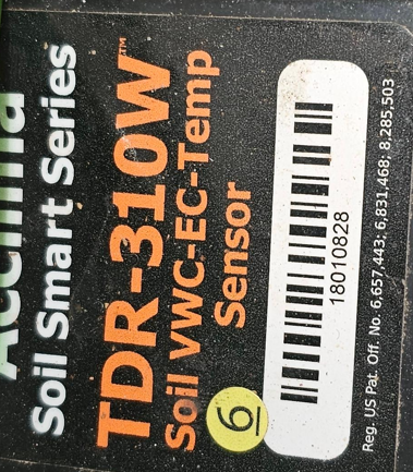
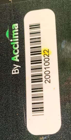
Depending on the model of Acclimaprobe being used, the address of the probe will either be the last digit of the Acclima probe’s serial number (which will be highlighted), or there will be a sticker on the probe housing denoting its address.
Example of sticker denoting Acclima sensor address:
Example of last highlighted digit denoting Acclima sensor address:
Comparing Capacitance-Based Sensors to Acclima Sensors
Capacitance-based sensors and TDR sensors utilize different modes of action to determine the VWC and EC. As such, the sensors can provide different readings when plugged into the same substrate type. Acclima has released a study comparing the two probe types and their readings to further elucidate those differences:
https://acclima.com/understanding-acclima-tdr-soil-moisture-sensors
Warranty Info:
Acclima TDR sensors have a 2 year manufacturer's warranty (covered through Acclima) starting at the date of purchase. Further warranty information can be found at the link below:
Growlink Global Hardware Limited Warranty